22
RIS 400_700PE/PW EKO 3.0
www.salda.lt
[ lt ]
[ it ]
[ en ]
[ de ]
Nr.
Pavadini-
mas
Nome
Name
Kennzeich
-
nung
Funkcija ModBus
Funzione ModBus
ModBus func.
ModBus-Funktion
Data adresas Indirizzo dati Data address Datenadresse
Duomenų kiekis
Quantità dati
Quantity of data
Datenmenge
Aprašymas
Descrizione
Description
Beschreibung
Reikšmė
Valori
Values
Werte
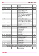
1
Antigelo
01h_Read_Coils
0
1
[ lt ]
- Plokštelinio šilumokaičio priešužšaliminė funkcija
[ it ]
- Funzione antigelo dello scambiatore a piastre
[ en ]
- Plate heat exchanger frost protection function
[ de ]
- Frostschutzfunktion des Plattenwärmetauschers
1-Attiva, o-Inattiva
2
Incendio
01h_Read_Coils
1
1
[ lt ]
- Ugnies pavojaus signalas
[ it ]
- Segnale allarme incendio
[ en ]
- Fire alarm
[ de ]
- Feuer-Alarm
1-Attiva, o-Inattiva
3
Filtri
01h_Read_Coils
2
1
[ lt ]
- Užsiteršusio filtro pavojaus signalas
[ it ]
- Segnale allarme filtri intasati
[ en ]
- Dirty filter alarm
[ de ]
-Schmutzfilter-Alarm
1-Attiva, o-Inattiva
4
Ventilatori
01h_Read_Coils
3
1
[ lt ]
- Ventiliatorių pavojaus signalas
[ it ]
- Segnale allarme ventilatori
[ en ]
- Fans alarm
[ de ]
- Lüfter-Alarm
1-Attiva, o-Inattiva
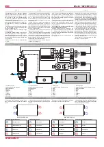
Pav. 4
F i g . 4
F i g . 4
Abb. 4
Mikrojungikliai 1 ir 2
Microinterruttori 1 e 2
Microswitches 1 and 2
Mikroschalter 1 und 2
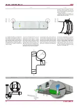
3 pav.
RS485_1 bei RS485_2. RS485_1
–
nuotolinio valdymo pultelio lizdas; RS485_2
– ModBus prievadas.
Stouch valdymo pultas privalo būti jungia
-
mas į RS485_2 (ModBus) jungtį
RJ10 lizdo kontaktų reikšmės:
1 – COM
2 – A
3 – l
4 – +24V
Valdymo plokštėje montuojami mikrojungikliai
1 ir 2 (pav. 4), varžų parinkimui derinant tinklą.
Derinimas priklauso nuo jungimo budo. Jei sujun-
giama žiedu, agregatų galėtų sujungti iki 30vnt.
Jei sujungiama kitaip, apie 7 agregatai. Tarp
pirmo ir paskutinio agregato turi būti 120...150Ω.
In fig. 3 sono indicati i due connettori RS485_1
(pannello comando remoto FLEX) e RS485_2
rete ModBus oppure pannello comando remoto
STOUCH.
Valore dei contatti del connettore RJ11:
1 – COM
2 – A
3 – B
4 – +24V
I microinterruttori 1 e 2 di fig.3 sono presenti
sulla scheda elettronica dell’unità (fig.4) e
permettono di selezionare la resistenza della
connessione ModBus. La regolazione dipende
dal tipo di connessione. Con una connessione ad
anello si possono collegare fino a 30 macchine,
con un altro schema al massimo 7. Ci deve
essere una resistenza di 120 ... 150 Ohm tra la
prima e l’ultima unità.
Fig. 3.
RS485_1 and RS485_2. RS485_1
:
remote control panel socked; RS485_2: Mod-
Bus port
Stouch control panel must be connected to
RS485_2 (ModBus) connection
RJ10 socket contacts reference:
1 – СОМ
2 – А
3 – В
4 – +24V
Microswitches 1 and 2 (Fig. 4) are mounted in
the control board for selecting of resistances du-
ring network adjustment. Adjustment depends on
the connection method. If the ring type connec-
tion is used, up to 30 units could be connected.
If other method is used, approximately 7 units
could be connected. The resistance between
the first and the last unit should be 120...150 Ω.
Abb. 3:
RS485_1 und RS485_2 RS485_1
:
Dose des Fernbedienpults RS485_2: ModBus-
Anschluss ON = Ein
Stouch Bedienteil muss an RS485_2 (Mod
-
Bus) angeschlossen werden
Bedeutungen der RJ10-Dosenkontakte:
1 – COM
2 – A
3 – l
4 – +24V
Auf dem Steuerpult werden Mikroschalter
1 und 2 (Abb. 4) montiert, indem man für die
Widerstandsauswahl den Netz anpasst. Die An-
passung hängt von der Verbindungsart ab. Wenn
man in einem Ring verbindet, können bis 30 Ag-
gregate verbunden werden. Wenn eine andere
Verbindungsart gewählt wird, können ungefähr
7 Aggregate verbunden werden. Zwischen
dem ersten und dem letzten Aggregaten muss
120...150Ω sein.
Varžos, Ω
Resistenza Ω
Resistance Ω
Widerstände, Ω
Jungiklis 1
Interruttore 1
Switch 1
1. Schalter
Jungiklis 2
Interruttore 2
Switch 2
2. Schalter
180
ON
ON
470
ON
OFF
330
OFF
ON

