background image

6

[ lt ]

[ ru ]

[ en ]

[ de ]

RIS 700_1200_1900_2200 HE/HW EKO 3.0

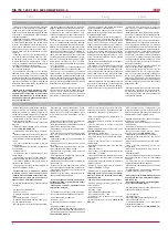
Il dispositivo è adatto all’installazione esclusi-

vamente nei in locali chiusi.

È vietato usare il dispositivo in ambienti poten-

zialmente esplosivi.

Il  dispositivo  è  destinato  a  immetere/estrarre 

solo aria pulita (ovvero priva di composti cor-

rosivi per metalli; di sostanze aggressive per lo 

zinco, per i materiali plastici, per la gomma; di 

sostanze, appiccicose e fibrose).

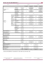
Temperatura  d’esercizio  e  umidità  dell’aspi-

razione  e  della  mandata  sono  indicate  nella 

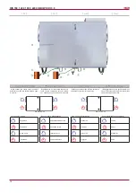
tabella (Fig. 1).

Устройство предназначено для работы в по-

мещении и на открытом воздухе (принадлеж-

ность: крышка).

Запрещается использование устройств в по-

тенциально взрывоопасной среде.

Устройство предназначено для подачи и вы-

тяжки из помещения только чистого воздуха 

(без  химических  соединений,  способствую-

щих коррозии металлов; без веществ, агрес-

сивных по отношению к цинку, пластмассе, 

резине; без частиц твердых, липких и волок-

нистых материалов).

Температура  и  влажность  вытяжного  и 

приточного  воздуха  приведены  в  табли-

це (Табл. 1).

Unit is designed to operate indoors and out-

doors (accessory: Roof).

It  is  forbidden  to  use  the  unit  in  potentially 

explosive environment.

Unit is designed to supply/extract only clean air 

(free of chemical compounds causing metal cor-

rosion, of substances aggressive to zinc, plastic 

and rubber, and of particles of solid, adhesive 

and fibred materials).

Extract and supply air temperatures and humid-

ity are given in the table (Tab. 1).

Das Gerät ist für Innen- und Außenaufstellung 

bestimmt (Dach als Zubehör, nicht im Lieferum-

fang erhalten).

Die Geräte dürfen nicht in einer explosionsge-

fährdeten Atmosphäre betrieben werden.

Das Gerät ist nur für die Zufuhr/den Abzug von 

ausschließlich sauberer Luft (ohne chemische 

Verbindungen, die Metallkorrosion hervorrufen; 

ohne aggressive Substanzen, die Zink, Kunst-

stoff und Gummi angreifen; ohne Partikeln von 

festen, klebenden sowie faserigen Materialien) 

in den/aus dem Raum gefertigt und bestimmt.

Abluft- und Zulufttemperatur sowie -feuchtigkeit 

sind in der Tabelle (Tab.1) angegeben.

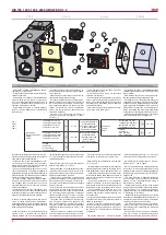
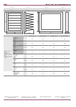
Fig. 1

Таб. 1

Tab. 1

Tab. 1

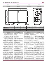
1

14

10

2

3

8

13

7

12

4

9

6

15

11

5

16

È consentito collegare dispositivi esterni di ven-

tilazione solo dopo aver garantito le necessarie 

condizioni imposte dal produttore: 

•  Dispositivi  che,  prima  dell‘installazione,  era-

no  conservati  nel  magazzino,  devono  essere 

ulteriormente  sigillati  per  impedire  l‘accumulo 

dell‘umidità all‘interno del dispositivo. 

• Se una volta installato il dispositivo non viene 

usato costantemente, è necessario impedire la 

penetrazione dell‘aria calda/umida attraverso le 

condotte d‘aria e la formazione della condensa 

all‘interno del dispositivo di ventilazione. 

•  le  unità  ventilanti  vengono  utilizzate  saltua-

riamente, al momento del riavvio è necessario 

che  vengano  fatte  funzionare  per  un’ora  alla 

massima velocità al fine di evacuare eventuali 

depositi di condensa.

•  Alimentando  la  macchina  l’elettronica  viene 

messa in tensione e se sono presenti batterie 

idroniche queste devono essere alimentate con 

acqua ed eventualmente acqua glicolata. 

In caso di mancato adeguamento alle prescri-

zioni di cui sopra il produttore ha il diritto di an-

nullare la garanzia, qualora un guasto dell’unità 

risulti causato dalla presenza di condensa sulla 

parte elettronica della stessa.

L’unità  può  lavorare  con  temperatura  dell’aria 

esterna  di  -40°  C  soltanto  con  una  batteria 

elettrica antigelo che porti la temperatura fino 

Когда температура наружного воздуха ниже 

-23 °гр. рекомендуем использовать электри-

ческий нагреватель.

Температура  рабочей  среды  обязательно 

должна быть между +5 и +40 ºC 

Эксплуатируемые вне помещений вентиля-

ционные установки включаются только тогда, 

когда обеспечиваются установленные изгото-

вителем обязательные условия:

• Герметичность установок, которые перед 

монтажом складируются на объекте, должна 

быть  обеспечена  с  помощью  дополнитель-

ных средств во избежание накопления влаги 

внутри установки.

• Если установка после монтажа не вводится 

в постоянную эксплуатацию, обязательно не-

обходимо обеспечить, чтобы в вентиляцион-

ную установку через воздуховоды не попадал 

теплый/ влажный воздух, и чтобы не проис-

ходила конденсация влаги внутри установки.

• В случае если установка не эксплуатиру-

ется  в  течение  длительного  времени,  или 

если вентиляционные установки включают-

ся редко, систему обязательно необходимо 

продувать на полной мощности 1/24 h – про-

сушивать.

•  Инсталлировано  и  подключено  напряже-

ние  к  автоматике  вентиляционной  установ-

ки, система водяных изделий наполнена гли-

It is recommended to use electrical pre-heater 

if the supply air temperature is below -23 

o

C.

Required ambient temperatures must be from 

+5 

o

C to +40 

o

C.

The air handling units installed outdoors shall be 

started only when the following obligatory condi-

tions established by the manufacturer are met:

• Units that are stored at the site before instal-

lation shall be sealed using additional means in 

order to prevent the accumulation of moisture 

inside the unit.

• If the unit is installed and is not started for 

ontinuous operation, it must be ensured that no 

warm/humid air enters the unit through air ducts 

and that no moisture condensates inside the unit.

•  If  the  ventilation  units  stand  idle  for  a  long 

time or are started infrequently, the system must 

be blown down at the maximum capacity 1/24 

h to dehumidify.

• Voltage to the automatics of the unit is installed 

and connected; the system of water products is 

filled with glycol/water.

In case of failure to comply with the require-

ments set out above, the manufacturer shall have 

the right not to apply the warranty in respect of 

the  occurrence  of  moisture/water  in  damaged 

components.

The unit can work at -40 ° C only with outdoor 

Bei Außentemperaturen unter -23 °C ist es zu 

emphehlen ein Vorheizrgeister zu benutzen.

Temperatur  der Arbeitsumgebung  muss  im 

Bereich von +5…+40 °C liegen.

Die im Freien betriebenen Lüftungseinrichtun-

gen werden nur dann eingeschaltet, wenn alle 

obligatorischen, durch Hersteller angegebenen 

Bedingungen  gewährleistet  sind.  Die  Bedin-

gungen sind:

• Die bevor Montage in Baustelle gelagerten 

Einrichtungen  sollen  zusätzlich  verdichtet 

werden,  um  die  Feuchtigkeitsansammlung  in 

Einrichtung zu vermeiden.

• Wird die Einrichtung montiert, doch instand 

nicht gesetzt, so soll der Durchfluss von warmer 

bzw.  feuchter  Luft  in  Lüftungseinrichtungen 

verhindert werden, um Kondensatansammlung 

in Einrichtung zu vermeiden.

• Werden die Lüftungseinrichtungen nur selten 

betrieben oder Betriebspausen ausgesetzt, so ist 

das System einmal in 24 Stunden mit maximaler 

Leistung zu belüften und zu trocknen.

•  Die  Steuerungselektronik  der  Lüftungsein-

richtung  ist  montiert  und  stromgespeist.  Das 

Wassersystem ist mit Mischung von Glykol und 

Wasser befüllt.

Der  Hersteller  übernimmt  keine  Gewährleis-

tung,  die  im  Folge  der  Nichtbeachtung  oben 

genannten Anweisungen und daraus resultieren-

Immissione

Приточный воздух 

Supply

Zuluft

- temperatura min./max.

- температура мин./макс.

- temperature min./max.

- Temperatur min./max.

[°C]

-3 / +40

con batteria elettrica di 

preriscaldamento 

без преднагревателям 

Without preheater

Ohne Vorheizregister

- temperatura min./max.

- температура мин./макс.

- temperature min./max.

- Temperatur min./max.

[°C]

-40 / +40

senza batteria elettrica di 

preriscaldamento 

c преднагревателям 

with preheater

Mit Vorheizregister

- umidità

- влажность

- max. humidity

- max. Feuchtigkeit

[%]

90

Estrazione

Extract

Abluft

- temperatura min./max.

- температура мин./макс.

- temperature min./max.

- Temperatur min./max.

[°C]

+15 / +40

- umidità

- влажность

- max. humidity

- max. Feuchtigkeit

[%]

60

Summary of Contents for RIS 700HE/HW EKO 3.0

Page 1: ...ubject to technical modification RIS 700_1200_1900_2200 HE HW EKO 3 0_P0017_AP_0002 Manuale di uso e manutenzione it ru Technical manual en Bedienungsanleitung de CENTRALE DI VENTILAZIONE CON RECUPERO...

Page 2: ...AVS 16 Unit di controllo 16 Protezione del sistema 18 Uso dell unit un una rete BMS 19 Indirizzi ModBus 20 Connessione elettrica dell unit HVAC 21 Guida per la riparazione del sistema 22 Guasti princ...

Page 3: ...nection diagram 32 Product maintenance table 34 Inhalt Transport und Lagerung 4 Beschreibung 4 Schutzmassnahmen 4 Bestandeile des Ger tes 5 Betriebsbedingungen 5 Bedienung 6 Filter 6 Ventilator 6 W rm...

Page 4: ...protect the product during shipping It is recommended to remove the protective film after the shipping otherwise the product may get signs of oxidation Alle Ger te sind werksseitig so verpackt dass s...

Page 5: ...st grunds tzlich verboten Arbeiten des Elektroanschlusses unter Spannung durchzuf h ren Wenn die Anschlussklemmen abgeschaltet sind ist das Schutzniveau IP00 So kann man Komponente ber hren die die ge...

Page 6: ...con temperatura dell aria esterna di 40 C soltanto con una batteria elettrica antigelo che porti la temperatura fino 23 5 40 C 1 24 h It is recommended to use electrical pre heater if the supply air t...

Page 7: ...della vita del motore Scollegare il ventilatore dall unit necessario ispezionare accuratamente la ventola del ventilatore controllando altre che non si sia accumulata della polvere o aitre so stanze...

Page 8: ...rom the heater and remove the heater Pic a b Das Elektro Heizregister bedarf keiner zus tz lichen Wartung Es sind nur die Filter rechtzeitig zu wechseln wie oben aufgef hrt Heizregister verf gen ber 2...

Page 9: ...nale di controllo control input Steuerungsignal VDC 0 10 0 10 classe di protezione protection class Schutzart IP 44 IP 54 Potenza assorbita generale Total power consumption Total Leistungsaufnahme pot...

Page 10: ...ontrol input Steuerungsignal VDC 0 10 classe di protezione protection class Schutzart IP 54 Potenza assorbita generale Total power consumption Total Leistungsaufnahme potenza corrente power current Ne...

Page 11: ...imensioni dei Filtri Filter class and dimen sions Filterklasse und Abmes sungen Di estrazione Exhaust Abluft M5 M5 M5 M5 Larghezza Width Breite L mm 600 650 692 692 Altezza Height H he H mm 250 415 52...

Page 12: ...d environment Installation must be performed in such manner that the weight of the air duct system and its com ponents would not overload the ventilation unit Enough space must be left during installa...

Page 13: ...mounted below the AHU s 1 level Nach dem Montieren des WRG Ventilators 1 an der Wand mu das Ablaufsystem des Kondensats angeschlossen werden Dazu muss das Endst ck 2 am Kondensatablauf des WRG Ventil...

Page 14: ...der Bedienseite aus betrachtet Fortluft Abluft Aussenluft Zuluft Depends on version of the ordered outdoor air can be taken from the left or right side L ftungsger te k nnen je nach bestellter Ver sio...

Page 15: ...ensor for extract air M1 actuator of by pass damper PS1 supply air differential pressure switch PS2 extract air differential pressure switch PS3 Heat exchanger antifrost pressure swich TE Exhaust air...

Page 16: ...00 K hler Warmwasserregister Kasten Comfort Box 400 SP Attuatore della serranda Actuator for dampers Klappenmotor 1141 SPs Attuatore della serranda con ritorno a molla Spring return actuator for dampe...

Page 17: ...Pa 0 60 TJ T1 TV VV 2 M4 M5 24VAC 3 M6 Esempio Example Exempel La temperatura dell aria di mandata pu essere regolata in base alla temperatura mi surata dal sensore dell aria di mandata e alla tempera...

Page 18: ...l von 0 10V DC bedient Funktion BOOST Die Ventilatoren werden mit einer maxima len Geschwindigkeit angelassen auf dem Bedienpult FLEX wird die BOOST Funktion dargestellt Die BOOST Funktion ist nicht a...

Page 19: ...o il valore del regolatore PI inferiore al valore impostato vd paragrafo II 6 4 3 della descrizione Flex Ventilazione possibile impostare 3 tipi di ventilazione vd paragrafo II 6 3 della Flex in base...

Page 20: ...anto non siano stati danneggiati Lo scatto della protezione termica automati ca solitamente avviene a causa di velocit del ventilatore troppo bassa ventilatore guasto serranda su presa d aria con attu...

Page 21: ...1 1 Schaiter Interruttore 2 2 Switch 2 2 Schaiter 180 ON ON 470 ON OFF 330 OFF ON Abb 3 RS485_1 und RS485_2 RS485_1 Dose des Fernbedienpults RS485_2 ModBus Anschluss ON Ein Stouch Bedienteil muss an...

Page 22: ...n Outside air damper actuator de Antrieb der Au enluftklappe 0 90 14 Preheater 01h_Read_Coils 12 1 it Indicazione della batteria di preriscaldamento ru en Preheater indication de Anzeige des Vorheizer...

Page 23: ...metern der Anlage gew hlt werden falls die Speiselei tung der Anlage fern vom Aggregat ist ist es n tig denAbstand und Spannungsfall zu bewerten Die Anlage muss unbedingt geerdet werden Steuerpult mus...

Page 24: ...ir TJ temp sensor 21 22 X16 6 11 12 13 14 15 16 17 N L 19 X16 5 M2 M3 17 18 L N N L L 16 20 15 230V AC 230V AC ON OFF ON OFF L control N L control L Supply air Extract air damper actuator damper actua...

Page 25: ...25 lt ru en de RIS 700_1200_1900_2200 HE HW EKO 3 0 Set 5 o C...

Page 26: ...315 mA pr fen Guasto dei connettori elettrici del dispositivo Possible unit fauit at electrical connections of the unit St rung in elektrischen Verbindungen Anschl ssen des Aggregats it Verificare pr...

Page 27: ...ienpuit oder RG1 Regler auszutauschen Il i ventilatore ventilatori non funziona non funzionano Fan s not working Ventilator en nicht funktioniert Guasto del ventilatore dell aria immessa PV o quella e...

Page 28: ...sul termostato Se la temperatura dell aria di mandata bassa controllare la centrale termica ru 1a 4 1 2a en Switch off the supply voltage Disconnect the respective sensor plug from the automation Meas...

Page 29: ...29 lt ru en de RIS 700_1200_1900_2200 HE HW EKO 3 0...

Page 30: ...o elettrica rotore Electric preheater rotor ON OFF 230V 50Hz Elektrovorheizer Rotor EIN AUS 230V 50Hz O 16A 100 X12 Tensione del ventilatore alla velocit attuale Voltage of Normal speed for air fans S...

Page 31: ...hlers X33 3 VAL Apertura della valvola della batteria PWM 24v 50hz PWM 24v 50hz Cooling valve opening PWM 24v 50hz ffnen der K hlungsklappe PWM 24v 50hz AO X33 4 VAL Chiusura della valvola della batte...

Page 32: ...ore della temperatura dell aria esterna Fresh ambient air temperature sensor Temperatursensor der frischen Luft der Au enluft X33 21 T OUT Sensore esterno Outdoor sensor Au ensensor AI X33 22 COM COM...

Page 33: ...our factory is pre run and tested before leaving and is shipped in good working order and condition We therefore extend to the original purchasers the following Warranty for the period of two years fr...

Page 34: ...16 3 ALARM X33 11 COM ANTI F Fan fall 1 2W max 4 5 6 10 9 X16 4 24 1 2W max Fan run 11 12 COM FAN 25 24 P 23 X29 X25 N L F1 3 1 P DX Cooling B 0 10 COM 14 11 G M5 24VAC 3 position Y2 Y1 VAL VAL VAL X3...

Page 35: ...E PE N L PE N L PV GND 0 10V in X32 X33 CE7 7 X16 7 PE N L1 L1 N PE L1 N PE L1 N PE 1f 230V AC Power supply cable X16 36 36 28 25 20 22 23 24 24 23 22 23 24 X16 4 25 25 31 30 X16 7 29 34 33 32 35 36 3...

Page 36: ...36 lt ru en de RIS 700_1200_1900_2200 HE HW EKO 3 0...

Page 37: ...37 lt ru en de RIS 700_1200_1900_2200 HE HW EKO 3 0...

Page 38: ...V Y2 Control CLOSE AC 24 V G System potential AC 24 V 24VDC X16 1 2 1 3 X33 5 X33 4 X33 3 VAL VAL VAL Y1 Y2 24VAC 3 position M5 G 11 14 COM B 0 10 4 5 6 7 X21 2 1 2 PS1 PS2 DX Cooling P 1 3 L N X25 X2...

Page 39: ...PE L1 L2 L3 N PE 1 2 3 4 5 6 7 8 9 9 8 7 6 5 4 3 2 1 X4 X3 PE N L K1 11 K1 14 PV GND X32 10A F1 1 2 T set COM X33 23 X33 24 26 27 28 P Transmitter 2 24 VDC 26 24V DC 27 intput 0 10V DC 28 GND L1 PE N...

Page 40: ...ituzione dei filtri Filter replacement Filterwechsel Ogni 3 4 mesi 3 4 Every 3 4 months Alle 3 4 Monate NOTA L acquirente del prodotto ha l obbligo di compilare la Tabella di manutenzione del prodotto...

Reviews: