background image

13

RIS 700PE/PW EKO 3.0

www.salda.lt

Рекуператор (1) строится на основание так, 

чтобы  сторона  рекуператора  (1)  с  трубкой 

отвода конденсата (2)  стояла 0 - 3 градусов 

ниже чем другая сторона. Сторона рекупера-

тора (1) с трубкой отвода конденсата не может 

быть ниже, чем другая сторона рекуператора! 

Трубами (4) (металлическими, пластиковыми 

или резиновыми) соедините рекуператор (1), 

сифон (3), и канализационную систему. Трубы 

(4) должны иметь, не меньше чем (3) градуса 

наклона вниз (1 метр трубы должен быть на-

клонен вниз на 55 мм)! 

Необходимо использовать сифон  с об-

ратным клапаном (Принадлежност).

Система отвода конденсата эксплуатируется 

в помещениях, где температура не достигает 

0°С!  Если  температура  ниже  чем  0°С,  то 

система  отвода  конденсата  должна  быть 

изолированна тепловой изоляцией или обо-

рудован подогрев.

Сифон  (3)  надо  устанавливать  ниже  чем 

рекуператор (1). 

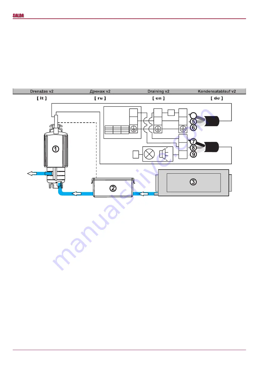
AHU (1) is built on a foundation in a such way 

that the side of AHU (1) with drainage exhaust 

pipe (2) is lower 0° - 3° than the other side. The 

side of AHU with drainage pipe can not be higher 

than the other side. 

The system must be connected with pipes (4) 

in such order: AHU (1), siphon (3) and sewerage 

system.  Pipes  (4)  should  be  bended  not  less 

than  3°  (1  meter  of  pipe  must  be  bended  55 

mm downwards)! 

It is necessary to use funnel trap for a drip-

ping condensate (Accessorie).

Draining  system  must  be  installed  in  the 

premise where the temperature is not lower than 

0°C. If temperature falls below 0°C the draining 

system should be isolated with thermal isolation 

or heating installed. 

The  siphon  (3)  must  be  mounted  below  the 

AHU (1) level.

Das  WRG-Gerät  (1)  wird  so  montiert,  dass 

die Seitenwand des WRG-Gerätes (1) mit dem 

Auslassrohr des Kondensates (2) mit 0 - 3 Grad 

niedriger als die andere Seitenwand steht. Die 

Seitenwand des WRG-Gerätes (1) mit dem Aus-

(1) mit dem Aus-

 mit dem Aus-

lassrohr des Kondensates darf nicht höher als 

die andere Seitenwand stehen! Dann die Rohre 

(Metall-, Plastik oder Gummirohre) (4) sowie in 

angegebener Reihenfolge das WRG-Gerät (1), 

Siphon  (3)  und  das Abwassersystem  zusam-

menschließen. Die Rohre (4) sollten mindestens 

mit  einem  Winkel  von  (3)  Grad  verlaufen  (1 

Meter es Rohrs sollte 55mm Gefälle haben). 

Es  ist  notwendig,  Siphon  für  tropfende 

Kondensat  zu  verwenden  (Zubehör).


Das 

Ablaufsystem  darf  nur  in  Räumen  betrieben 

werden, in welchen die Raumtemperatur nicht 

unter 0°C sinkt! Ansonsten muss das System mit 

thermisch isoliert werden.

Der  Siphon  (3)  muss  unterhalb  des  WRG-

Gerätes (1) montiert werden.

L

N

N

N

L

L

NC

NO

C

N

1A

4

1. Vandens siurblys

2. Automatinis siurblio įjungėjas

3. Rekuperatorius

4. Rudas

5. Mėlynas

6. Žalias

7. Juodas

8. Geltonas

9. Raudonas

1. Водяной насос

2. Автоматический включатель для насоса

3. Рекуператор

4. Kоричневый

5. Cиний

6. Зелёный

7. Черный

8. Желтый

9. Kрасный

1. Water pump

2. Automatic switch for water pump

3. AHU

4. Brown

5. Blue

6. Green

7. Black

8. Yellow

9. Red

1. Wasserpumpe

2. Automatische Schalter für Wasserpumpe

3. WRG-Ventilatoren

4. Brown

5. Blau

6. Grün

7. Schwarz

8. Gelb

9. Red

Rekuperatorius  (1)  ant  pagrindo  statomas 

taip, kad rekuperatoriaus (1) šonas su konden-

sato  išleidimo  vamzdeliu  (2)  būtų  0  -  3  laips-

niais  žemiau  už  kitą  šoną.  Rekuperatoriaus 

(1)  šonas  su  kondensato  išleidimo  vamzdeliu 

negali būti aukščiau kito šono!

Vamzdžiais (4) (metaliniais, plastikiniais arba 

guminiais)  tarpusavyje  sujungti  nurodyta  tvar-

ka rekuperatorių (1), sifoną (3) ir kanalizacijos 

sistemą.

Vamzdžiai (4) turi turėti ne mažesnį nei 3 laips-

nių kampo nuolydį (1 metras vamzdžio turi būti 

pakrypęs į apačią 55mm)!

Būtina  naudoti  sifoną  su  atgalinės  eigos 

vožtuvu(Priedas).

Kondensato  nuvedimo  sistema  turi  būti  eks-

ploatuojama  patalpose,  kuriose  aplinkos  tem-

peratūra negali būti žemesnė nei 0°C! Jei aplin-

kos  temperatūra  gali  nukristi  žemiau  0°C,  tai 

sistemą  reikia  izoliuoti  šilumine  izoliacija  arba 

įrengti šildymą.

Sifonas  (3)  turi  būti  žemiau  rekuperatoriaus 

(1) lygio.

Summary of Contents for RIS 700PE EKO 3.0

Page 1: ...und Design sind vorbehalten Subject to technical modification RIS 700PE PW EKO 3 0_P0023_AA_0003 REKUPERATORINIAI RENGINIAI AHU WITH HEAT RECOVERY L FTUNGSGER TE MIT W RMER CKGEWINNUNG RIS 700PE PW EK...

Page 2: ...gimas 21 Rekomendacijos sisistemos derinimui 22 Pagrindiniai VOK renginio gedimai ir j alinimo b dai 24 Valdymo plok t RG1 27 LED valdiklio indikacijos 28 Valdiklio ir sistemos mazg sutartiniai ym jim...

Page 3: ...3 0 35 Product maintenance table 36 Inhalt Transport und Lagerung 4 Beschreibung 4 Schutzmassnahmen 4 Bestandeile des Ger tes 5 Betriebsbedingungen 5 Bedienung 6 Filter 6 Ventilator 6 W rmetauscher 7...

Page 4: ...tigung des Fremdk rpers Stillstand des Laufrades abwarten und die Hei zung abk hlen lassen Gegen Wiedereinschalten Rekuperatoriai tai oro v dinimo renginiai kurie valo ildo ir tiekia vie i or renginia...

Page 5: ...pluo tini med iag Unit is designed to operate indoors only It is forbidden to use the unit in potentially explosive environment Unit is designed to supply extract only clean air free of chemical compo...

Page 6: ...ischen Bedienung beachten In der Motorkonstruktion sind hochwertige Lager eingebaut Die Lager sind eingepresst und erfordern keine Schmierung Ventilator von der Anlage abschalten Die Fl gel vom Ventil...

Page 7: ...l angreifen k nnten Fl gel und Geh use danach mit viel Wasser gr ndlich reinigen keine Hochdruckanlage Putzmittel scharfes Werkzeug oder aggressive Stoffe verwenden die zu Kratzer und Besch digungen f...

Page 8: ...r manuellen R ckstellung die bei 100 C anspricht Bei Ansprechen der Schutzvorrichtung mit ma nueller R ckstellung ist das Ger t vom Strom netz zu trennen Abwarten bis die Heizk rper sich abgek hlt hab...

Page 9: ...urrent Nennleistung Nennstrom kW A 1 54 8 34 3 34 15 84 4 84 9 34 0 34 2 84 Valdymo automatika sumontuota Automatic control integrated Integriertes Steuerungsystem iluminis na umas Thermal efficiency...

Page 10: ...H he H mm 210 Gylis Depth Tiefe L2 mm 46 Tiekimo supply Zuluft F7 Plotis Width Breite L mm 445 Auk tis Height H he H mm 210 Gylis Depth Tiefe L2 mm 46 Filtro modelis Filter model Filter Modell MPL mo...

Page 11: ...f hren dass durch das Gewicht des Luftleitungssystems und aller seiner Bauteile keine Belastungen am L ftungs ger t auftreten Bei der Montage ist ein ausreichender Schwenk bereich f r die Wartungst r...

Page 12: ...ie Umformer der Luftqualit t falls sie zus tzlich verwendet werden sollen m glichst weit von den L ftungsanlagen montiert werden je nach der Kabell nge des Sensors bis zur ersten Scheidung Biegung des...

Page 13: ...f lle haben Es ist notwendig Siphon f r tropfende Kondensat zu verwenden Zubeh r Das Ablaufsystem darf nur in R umen betrieben werden in welchen die Raumtemperatur nicht unter 0 C sinkt Ansonsten muss...

Page 14: ...amo oro temperat ros jutiklis tiekia mas kartu su integruota automatinio valdymo sistema TL vie io oro temperat ros jutiklis tiekiamas kartu su integruota automatinio valdymo sis tema TE alinamo oro t...

Page 15: ...hut off damper SKG Schliessklappen SKG VVP VXP RIS 700PW EKO 3 0 2 3 eigis vo tuvas 2 3 2 3 way valve 2 3 Wege Ventil CO2 CO2 keitiklis CO2 CO2 transmitter CO2 sender S 1141 Skirtuminio sl gio keitikl...

Page 16: ...ngia mas ildytuvas elektrinis arba vandeninis ir nei jungiamas vandeninio variantu atidarin ja mas u darin jamas ildytuvo vo tuvas tol kol pasiekiama nustatytoji temperat ra Tiekiamo oro temperat rai...

Page 17: ...ooling by ventilation Two types of cooling exist using halocarbon or water cooler Cooling is based on the algorithm of the PI regulator and is activated when there is need for cooling Conditions for a...

Page 18: ...vice cover of the heater When manual thermal protection is triggered fans operate in maximum capacity until the manual heater protection is reset by pressing the reset button and the device is restart...

Page 19: ...X installer description Fig 3 RS485_1 and RS485_2 RS485_1 remote control panel socked RS485_2 Mod Bus port Stouch control panel must be connected to RS485_2 ModBus connection RJ10 socket contacts refe...

Page 20: ...kiamo oro temperat ros jutiklio pavojaus signalas ru en Supply air temperature sensor alarm de Zuluft Temperatursensor Alarm 1 active o passive 9 RH 01h_Read_Coils 9 1 lt DTJ 100 1 dr gnumo jutiklio p...

Page 21: ...nius parametrus jei renginio maitinimo linija yra toli nuo agregato b tina vertinti atstum ir tampos kritim renginys b tinai turi b ti emintas Sumontuokite valdymo pulta numatytoje vietoje Nutieskite...

Page 22: ...s und Einstellungsarbeiten der Anlage m ssen bis zur bergabe an den Benutzer nur durch entsprechend qualifizierte und geschulte Fachkr fte ausgef hrt werden Falls man w n scht dass das automatische St...

Page 23: ...pply air water heater is used it is necessary to prop erly install antifreeze protection from possible freezing of heat carrier Antifreeze temperature sensor TV must be mounted in clamp on return pipe...

Page 24: ...utomatische Schalter F eingeschaltet sind Sicherung des RG1 Reglers 315 mA pr fen Gedimas agregato elektros sujungimuose jungtyse Possible unit fault at electrical connections of the unit St rung in e...

Page 25: ...uschen Neveikia ventiliatorius iai Fan s not working Ventilator en nicht funktioniert Tiekiamo PV arba i traukiamo IV oro ventiliato riaus gedimas PV IV Supply PV or extracted IV air fan fault St rung...

Page 26: ...off the supply voltage Disconnect the respective sensor plug from the automation Measure and check the sensor voltage using the bellow dependency Fig 1a If measure ment results do not correspond with...

Page 27: ...27 RIS 700PE PW EKO 3 0 www salda lt...

Page 28: ...ytuvas Electric heater Elektroheizer O 16A 100 X29 Elektrinis pa ildytuvas rotorius Electric preheater rotor ON OFF 230V 50Hz Elektrovorheizer Rotor EIN AUS 230V 50Hz O 16A 100 X12 Esamo grei io venti...

Page 29: ...AO 100mA DX Freoninio au intuvo arba vandeninio ildytuvo cirkuliacinio siurblio valdymas DX cooler or water heater circulatory pump control Kontrollieren des Freonk hlers bzw der Zirkulationspumpe von...

Page 30: ...peratursensor AI X38 2 COM X40 1 5V X40 2 I traukiamo oro santykin s dregm s jutiklis Extract air humidyti sensor Abluft Feuchtigkeitssensor AI X40 3 COM TJ Tiekiamo oro temperat ros jutiklis Supply a...

Page 31: ...wlege or consent These conditions are readily discern able when the equipment is returned to our factory for inspection If equipment is found to be faulty or a break down occured the purchaser should...

Page 32: ...er FA 7 2 1 X21 YE GN BU RD PWM STOP NO START NC X33 15 X33 16 COM A 0 10 L X31 24VDC 24VDC X41 1 X41 2 X39 2 X39 1 X38 1 X38 2 X40 3 X40 2 X40 1 X34 8 X34 7 X34 6 X34 5 X34 4 X34 3 X34 2 X34 1 X33 26...

Page 33: ...ty transmitter FA Jumper A2 A1 A2 A1 7 2 1 X21 YE GN BU RD PWM STOP NO START NC X33 15 X33 16 COM A 0 10 L X31 24VDC 24VDC X41 1 X41 2 X39 2 X39 1 X38 1 X38 2 X40 3 X40 2 X40 1 X34 8 X34 7 X34 6 X34 5...

Page 34: ...Green Blue YE Yellow 5V TA COM RH RD WH YE GY RH U TA Jumper FA 7 2 1 X21 YE GN BU RD PWM STOP NO START NC X33 15 X33 16 COM A 0 10 L X31 24VDC 24VDC X41 1 X41 2 X39 2 X39 1 X38 1 X38 2 X40 3 X40 2 X...

Page 35: ...C 11 14 X16 3 7 8 R1 A1 A2 M4 1f 230V AC PE L N 3 1 P DX Cooling Jumper BOOST STOP NO START NC Transmitter 1 24 VDC 23 24V DC 24 intput 0 10V DC 25 GND Fan fall 1 2W max 1 2W max Fan run P 24VDC 24VDC...

Page 36: ...imas Filter replacement Filterwechsel Kas 3 4 m nesius 3 4 Every 3 4 months Alle 3 4 Monate PASTABA Produkt sigij s asmuo privalo pildyti Gaminio prie i ros lentel NOTE The purchaser is required to fi...

Reviews: