8
SIG 6-17
www.salda.lt
ATTENTION!
Setup, installation, confi guration, and initial start up of the heat pump system must be carried
out by
a qualifi ed technician
applying the relevant statutory rules, regulations, and guidelines, as well as the operat-
ing instructions.
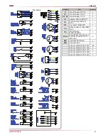
Electrical circuit diagrams are shown in chapter 10.4.
The following electrical connections must be established on the heat pump:
1.Main cable to the control panel of the heat pump (see pic. 4.5);
2.DHW control temperature probe B3 (connection ports 45 and 46, see pic. 4.5);
For additional functions the probes and components can be connected:
1. Outside air temperature probe B6 (connection ports 49 and 50, see pict. 4.5);
2. Mixed system outlet temperature probe B8 (connection ports 53 and 54, see pic. 4.5);
3. System 3-way valve (connection ports 38,39 and 40, see pic. 4.5);
4. Flow switch (brine) (connection ports 29 and 30, see pic. 4.5);
5. DHW storage integrated heater (8A resistive) (connection ports 10 and 11, see pic. 4.5);
6. System integrated heater/boiler (8A resistive) (connection ports 15 and 16, see pic. 4.5);
7. Mixed circuit pump (connection ports PE,N and 9, see pic. 4.5).
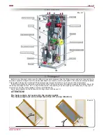
The main cable and all additional cables must be connected as shown in picture 4.4.
In SIG type heat pump is installed scroll type compressor. It can only compress in one rotational direction. Three-
phase compressors can rotate in either direction depending upon phasing of the power. There is a 50/50 chance of
connecting power incorrectly in such a way to cause rotation in the reverse direction and damage compressor. To
avoid this, there is instaled a 3-phase control measurement relay. When pluging the main power suply cable, 3-phase
control measurement relay lights yelow (green) color, if light fl ashes (or lights red) it is necessary to reverse two
phases.
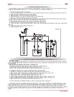
When fi lling the collector system mix the water with antifreeze in an open container. The mixture should be protect-
ed against freezing down to about -15 °C. The brine is fi lled by connecting a fi lling pump.
1. Check the collector system for leakage.
2. Connect the fi lling pump 7 and return line on the collector system’s service connections as shown in picture 4.3.
3. Close the valve 4 between the service connections.
4. Open the valves 5 and 6 on the service connections.
5. Start the fi lling pump 7 and fi ll until there is fl uid in the return pipe.
6. Swith on a brine circulation pump from control board.
7. The fi lling pump and the heat pump’s brine pump are now operational. The fl uid should circulate via the mixing
container until it emerges from the return hose without being mixed with air.
8. Stop the fi lling and heat pump’s brine pump and clean the particle fi lter.
9. Start the fi lling pump, open the valve between the service connections.
10. Close the valve 5 on the service connection’s return line. Now pressurise the system (to max 3 bar) with the fi ll-
ing pump.
11. Close the valve 6 on the service connection.
12. Stop the fi lling pump 7.
Pic. 4.3
Summary of Contents for SIG 6-17
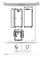
Page 13: ...13 SIG 6 17 www salda lt Pic 10 1 Outside temperature sensor Temperature sensor...
Page 20: ...20 SIG 6 17 www salda lt Pic 10 4 1...
Page 21: ...21 SIG 6 17 www salda lt Pic 10 4 2...
Page 22: ...22 SIG 6 17 www salda lt Pic 10 4 3...
Page 24: ...24 SIG 6 17 www salda lt Pic 10 5 1 Pic 10 5 2 Domestic hot water Direct Heating system...
Page 29: ...29 SIG 6 17 www salda lt...


