12
Smarty 3X VE / Smarty 3X VE 3.0
www.salda.lt
• Installing should only be performed by qualified and trained staff.
• The unit must be installed firm and tight, it will ensure its safe use.
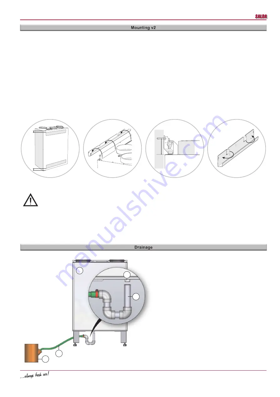
• When installing the unit on the wall prepared accessories should be used for that purpose as shown (Pic. 2). The unit mounted on the wall shouldn’t
be leaning.
• Before connecting to the air duct system, the connection openings of ventilation system air ducts shall be closed.
• When connecting air ducts, consider the directions of air flow indicated on the casing of the unit.
• Do not connect the elbows in vicinity of the connection flanges of the unit. The minimum distance of the straight air duct between the unit and the first
branch of the air duct in the suction air duct must be 1xD, in air exhaust duct 3xD, where D is diameter of the air duct.
• Installation shall be performed in such manner that the weight of the air duct system and its components would not overload the ventilation unit.
• Enough space 2xL (L is the depth of the unit) must be left during installation for opening of the maintenance door of the ventilation unit.
• It is recommended to install the unit on the wall of the room where the level of noise is not important.
• When installing the unit on the wall is necessary to isolate the wall additionally to suppress the noise and vibrations. Also isolate wall mounting
accessories from possible vibration.
• Install the control panel on the foreseen place according to the mounting instructions provided in control panel technical manual.
• Stretch the connection cable, which is included into standard package, between the control panel and control box. The cable of the control panel
can’t be stretched together with power cables. Due to insufficient control panel cable stretching disturbance between the unit and control panel can
be caused.
• Connect all necessary (including additionally ordered) accessories to the units control system X16 assembly.
When AHU (1) is already mounted the draining system has to be
connected. In order to do that the coupling (2) must be screwed to
the AHU draining chute (5). The system must be connected with me-
tal, plascic or rubber pipes (3) in such order: AHU (1), siphon (2) and
sewerage system (5). Pipes (3) should be bended not less than 3°
degrees (1 meter of pipe must be bended 55 mm downwards)! Befo-
re turning on AHU (1) the draining system should be filled up with at
least 0,5 l of water (siphon (2) must be always filled with water), also
check if water reaches sewerage system (4)! In other case premise
can be flooded.
Draining system must be installed in the premise where the tem-
perature is not lower than 1°C. If temperature falls below 0°C the
draining system should be isolated with thermal isolation.
The Siphon (2) not necessarily must be mounted below the AHU
(1), but below the 1st AHU level.
40
mm
90
90
c
a
b
d
10
mm
10
mm
Pic. 02
a) To reduce the vibration stick the insulating tape on the unit‘s casing side which touches the wall before mounting the unit on the wall.
b) The unit has to be mounted on the mounting brackets.
c) AHU mounting drawing.
d) After the unit is mounted two wall bracket tabs has to be folded to 90 angle by pliers to avoid the accident fall of the unit.
3
4
1
2
5


