background image

EN |

 29

SMARTY XV v2020.3

8.1.7. 

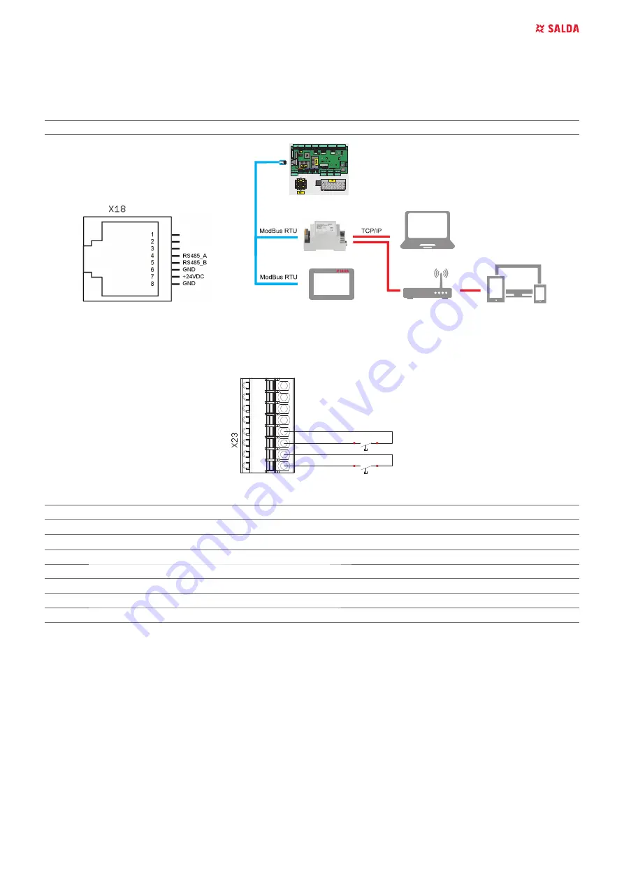
CONNECTION OF REMOTE CONTROL PANEL OR MODBUS

Wiring diagram.

Automation controller F zone, X18 connector.

6ZLWFKSRVLWLRQIRU;FRQQHFWRUFRQ¿JXUDWLRQ

Switch

Position

Purpose

S2

1

5OLQHWHUPLQDWLRQUHVLVWRU2Q2ႇ


8.1.8. 

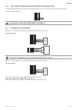
FIRE PLACE CONNECTION (SMARTY XV 1.1)

Wiring diagram.

Automation controller C zone, X23 connector.

1

234

5

678

-F

ireP

lace II

DI4

+

1

2VDC

+

1

2VDC

DI3

-F

ireP

lace I

LED indication

miniMCB

miniEX1

LED1

9PLQL0&%SRZHULQGLFDWLRQ:PRGH

LED1

EX1 status LED

LED2

9PLQL0&%SRZHULQGLFDWLRQ

LED3

9PLQL0&%SRZHULQGLFDWLRQ21PRGH

LED4

MiniMCB status LED

LED5

Communication line Transmit indication

LED6

Communication line Receive indication

LED7

24V peripheral POWER ON indication

Summary of Contents for SMARTY XV

Page 1: ...SMARTY XV EN MOUNTING AND INSTALLATION INSTRUCTION...

Page 2: ...15 6 1 SAFETY INSTRUCTIONS 15 6 2 GENERAL RECOMMENDATIONS FOR VENTILATION SYSTEM MAINTENANCE 15 6 3 COVER OPENING 15 6 4 FILTERS MAINTENANCE 16 6 5 FAN MAINTENANCE 16 6 6 HEAT EXCHANGER MAINTENANCE 17...

Page 3: ...information about the unit Figure 2 1 Technical label 1 Logo 2 Product code SKU 3 Product name 4 Technical data 5 Serial number 6 Production place Figure 2 2 Indication for duct connection ODA outdoo...

Page 4: ...PHQWV XQWLO WKH KDYHQ W FRROHG GRZQ 6RPH GHYLFHV DUH KHDY RX VKRXOG EH YHU FDUHIXO ZKLOH WUDQVSRUWLQJ DQG LQVWDOOLQJ WKHP 8VH VXLWDEOH OLIWLQJ HTXLSPHQW When connecting electricity to the mains a circ...

Page 5: ...WKH VWDQGDUG SDFNDJH Control functions depend on selected control board type MiniMCB or MiniMCB basic Product name Control board Type Heat recov ery Tempera ture control Bypass damper Optional heatin...

Page 6: ...0 100 150 150 150 150 F mm 34 34 80 80 80 80 d G3 8 G3 8 G1 2 G1 2 G1 2 G1 2 d1 mm 394 394 391 391 391 391 d2 mm 201 201 206 206 206 206 d3 mm 163 163 267 267 267 267 d4 mm 152 152 271 271 271 271 D1...

Page 7: ...4 7 9 0 34 2 7 Automatic control integrated miniMCB miniMCB basic miniMCB miniMCB basic miniMCB miniMCB basic QVXODWLRQ RI ZDOOV mm 30 30 30 30 30 30 KDXVW DLU OWHU FODVV GLPHQVLRQV LxWxH mm MPL 270x1...

Page 8: ...VNHW ZKLWH 605 mm 605 mm 1300 mm 1300 mm 1300 mm 1300 mm Sealing rubber 15x8x7 427021 66 mm 66 mm 610 mm 610 mm 610 mm 610 mm Straight Fiting With O ring F 1 2 M M 1 1 1 1 Rubber gasket d20xD28 s2mm 1...

Page 9: ...DQG ZDWHU The units must be transported to the storage place or installation site using forklifts The recommended storage i period should not be longer than one year In case of storing the units for...

Page 10: ...V 4XV F2 5 4 PIPING AND INSTRUMENTATION DIAGRAM Figure 5 4 1 SMARTY XV miniMCB Available in 3XV 4XV F2 1 1 models Check the manual for details Optional Figure 5 4 2 SMARTY XV miniMCB basic Only heater...

Page 11: ...RQ WKH GHYLFH KRXVLQJ VKRXOG EH REVHUYHG R QRW FRQQHFW WKH EHQGV FORVH WR FRQQHFWLRQ DQJHV RI WKH XQLW 7KH PLQLPXP GLVWDQFH RI WKH VWUDLJKW DLU GXFW EHWZHHQ WKH XQLW DQG WKH UVW EUDQFK RI WKH DLU GXFW...

Page 12: ...FLOOR MOUNTING Figure 5 7 1 RRU PRXQWLQJ RSWLRQDO DFFHVVRU UHTXLUHG 5 8 WALL MOUNTING OF THE UNIT b 30 mm a c d 90 90 Figure 5 8 1 mounting on the wall 5 9 DRAINAGE HIRUH HYHU KHDWLQJ VHDVRQ WKH FRQGH...

Page 13: ...WRU LV VLWXDWHG XSVWUHDP LQVWDOO D V VWHP ZLWK D FRQGHQVDWH SXPS R HUHG DV DQ DFFHVVRU DRAINAGE SYSTEM INSTALLATION SMARTY 3XV 4XV F2 1 Connect the drain couplings ZPGGM056 SDUW PDOH WR GUDLQDJH FRQQH...

Page 14: ...sportation 7KH SRZHU FDEOH FDQ EH UHSODFHG RQO E D TXDOL HG WHFKQLFLDQ KDYLQJ HYDOXDWHG WKH UDWHG SRZHU DQG FXUUHQW The manufacturer does not assume any liability for personal injuries and property da...

Page 15: ...QRW FDXVH QRLVH ZKHQ URWDWHG E hand 0DNH VXUH WKDW WKH IDVWHQLQJ VFUHZV DUH QRW ORRVH DQG IUHH RI mechanical damage Check electrical connections and make sure that these are se cured properly and are...

Page 16: ...lance Excessive imbalance may lead to ac FHOHUDWHG ZHDU RQ PRWRU EHDULQJV DQG YLEUDWLRQ OHDQ WKH LPSHOOHU DQG LQVLGH KRXVLQJ ZLWK D PLOG GHWHUJHQW ZDWHU DQG GDPS VRIW FORWK Do not use high pressure cl...

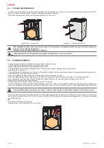
Page 17: ...WRR VWURQJ VWUHDP FDQ IROG WKH SODWHV 3ODFH EDFN WKH KHDW H FKDQJHU RQO ZKHQ LW LV FRPSOHWHO GU Figure 6 6 1 Smarty 2XV Figure 6 6 2 Smarty 3XV 4XV F2 87 21 WKH KHDW H FKDQJHU FDQ QRW EH XVHG ZKHQ WK...

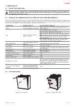
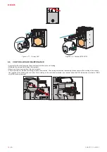
Page 18: ...LWKGUDZ WKH DXWRPDWLRQ WKURXJK WKH IURQW SDUW Disconnect the connectors from the control board The connectors are marked according to connection location Thus during automation reassembly please obse...

Page 19: ...TIONS OO PLQL0 FRQWURO ERDUGV DUH UXQ E WKH VDPH VRIWZDUH ZLWK DOO IXQFWLRQV LQFOXGHG XOO IXQFWLRQ OLVW DQG GHVFULSWLRQ RX FDQ QG RQ WKH 0 PLQL0 WHFKQLFDO PDQXDO RZHYHU RSHUDWLRQ DQG FRQWURO RI WKH GH...

Page 20: ...ACC004460 ACC004460 Router TP Link TL WR802N ACC000273 ACC000273 ACC000273 ACC000273 ACC000273 ACC000273 External sensors Sensor CO2 duct S KCO2 ACC000277 ACC000277 ACC000277 ACC000277 ACC000277 ACC00...

Page 21: ...2 ACC003802 EKA NIS 125 0 6 1 f ACC000319 ACC000319 EKA NIS 125 0 9 1 f ACC000320 ACC000320 EKA NIS 125 1 2 1f ACC003803 ACC003803 EKA NIS 125 1 5 1 f ACC000321 ACC000321 EKA NIS 125 1 8 1 f ACC000322...

Page 22: ...tion EKA NIS connection XWRPDWLF DQG PDQXDO SURWHFWLRQ PXVW EH FRQQHFWHG WR FRQWUROOHU V FRQQHFWRU ZKHQ DQ HOHFWULF KHDWHU LV HTXLSSHG ZLWK WKHVH FRQQHFWLRQ WHUPLQDOV 2WKHUZLVH MXPSHUV DUH LQVWDOOHG R...

Page 23: ...ts feature one connection of external electrical heater pre heater In factory settings the connection is intended for the pre KHDWHU KRZHYHU LW FDQ EH FRQ JXUHG IRU WKH KHDWHU HDWHU SUH KHDWHU FDQ EH...

Page 24: ...24 EN SMARTY XV v2020 3 EKA NIS connection...

Page 25: ...H FKDQJHG LQ WKH HQYLURQPHQW RI WKH 0 DWHZD WEB application service or on the ST SA Control panel Settings in the environment of the MB Gateway WEB application service KDQJH WKH VHWWLQJV DV IROORZV 6H...

Page 26: ...ection device modes NC by default 6 Go to Menu Service Digital inputs Preheater protection Set the manual and automatic protection device modes NC by default Pre heater installation diagram Installati...

Page 27: ...0VDC sensors Sensors connection 24VDC AI4 0 10V GND 1 2 3 4 5 6 7 8 AO1 GND Vin Transmiter 1 p 24VDC GND 1 2 3 AI1 0 10V Vin GND AO1 Transmitter 2 Smarty 3XV 1 1 and Smarty 4XV F2 1 1 come with the in...

Page 28: ...ING TO PETTENKOFER LIMIT 8 1 6 CONECTION OF SUPPLY AND EXHAUST AIR DAMPERS OO YHUVLRQV RI 6PDUW 3 FDQ EH HTXLSSHG ZLWK RXWGRRU DLU DQG H KDXVW DLU GDPSHUV DPSHUV DUH RSHUDWHG E 2SHQ ORVH DFWXDWRUV Ins...

Page 29: ...E CONNECTION SMARTY XV 1 1 Wiring diagram Automation controller C zone X23 connector 1 2 3 4 5 6 7 8 Fire Place II DI4 12VDC 12VDC DI3 Fire Place I LED indication miniMCB miniEX1 LED1 9 PLQL0 SRZHU LQ...

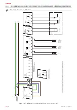
Page 30: ...30 EN SMARTY XV v2020 3 8 1 9 RECOMMENDED SCHEME FOR CONNECTION OF INTERNAL AND EXTERNAL COMPONENTS Only Smarty 1 1 versions have N2 module LJXUH 6PDUW 9 6PDUW 9 9 9 36...

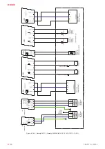
Page 31: ...EN 31 SMARTY XV v2020 3 LJXUH 6PDUW 9 6PDUW 9 9 9 36...

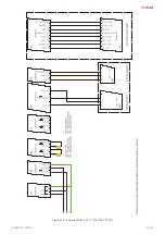
Page 32: ...32 EN SMARTY XV v2020 3 LJXUH 6PDUW 9 6PDUW 9 9 9 36...

Page 33: ...t 0 22 LJXUH SDVV 60 57 3 9 N 1 2 3 4 5 6 X25 7 8 794821 1 1 2 3 4 5 6 X3 KF2EDGKD 2 5 6P 1 2 3 4 5 6 X5 7 8 KF2EDGKD 2 5 8P 1 2 3 4 5 6 X29 7 8 794821 1 X12 KF2EDGKD 5 0 3P 3 2 1 Bypass Preheater Whi...

Page 34: ...9 7DFKR B 7DFKR B 7DFKR B 7DFKR B 1 PLQL0 9 KLWH 5HG KLWH 5HG HOORZ OXH HOORZ OXH URZQ _ ODFN UHHQ HOORZ OXH URZQ _ ODFN OXH UHHQ HOORZ Smarty 4XV F2 unit fans connect WR FRQWUROOHU ZLWK H WHQVLRQ ZL...

Page 35: ...HU RQWURO 9 3RZHU XS WR N I 9 0D N 9 3 1 2 1 PLQL0 9 1 2 9 1 PLQL0 9 WHUQDO SUHKHDWHU RQWURO 9 3RZHU RYHU N I 9 9 3 3 1 2 1 PLQL0 9 1 2 9 1 PLQL0 9 WHUQDO SUHKHDWHU RQWURO 9 3RZHU RYHU N I 9 9 3 3 1 9...

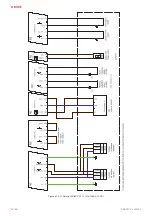
Page 36: ...36 EN SMARTY XV v2020 3 LJXUH 6PDUW 9 9 36...

Page 37: ...EN 37 SMARTY XV v2020 3 LJXUH 6PDUW 9 9 36...

Page 38: ...38 EN SMARTY XV v2020 3 LJXUH 6PDUW 9 9 36...

Page 39: ...not operat ing or malfunctioning if installed 7RR ORZ DLU RZ LQ DLU GXFWV DFWLYDWHV DXWR matic protection KHFN LI DLU OWHUV DUH QRW FORJJHG Check if fans are rotating Manual safety device is activated...

Page 40: ...k control standard 0 95 12 1 E 350 2085 HQWUDO GHPDQG FRQWURO RSW ZLWK VHQVRU 0 85 14 0 E 281 2098 RFDO GHPDQG FRQWURO RSW ZLWK VHQVRUV 0 65 17 2 E 164 2126 Declared typology Bidirectional Type of dri...

Page 41: ...YLVXDO OWHU ZDUQLQJ IRU 598 V Timer ErP Compliance 2018 Internet address for disassembly instructions ZZZ VDOGD OW MODEL SMARTY 3XV 1 1 Climate zone Control typology Control factor 6SHFL F HQHUJ consu...

Page 42: ...VXDO OWHU ZDUQLQJ IRU 598 V Timer ErP Compliance 2018 Internet address for disassembly instructions ZZZ VDOGD OW MODEL SMARTY 4XV F2 1 1 Climate zone Control typology Control factor 6SHFL F HQHUJ cons...

Page 43: ...HQWUDO GHPDQG FRQWURO RSW ZLWK VHQVRU 0 85 12 6 E 316 2052 Declared typology Bidirectional Type of drive installed fan Variable Type of heat recovery system Recuperative 7KHUPDO H FLHQF RI KHDW UHFRYH...

Page 44: ...al ventilation Part 7 Performance test ing of a mechanical supply and exhaust ventilation units including heat recovery for mechanical ventilation systems intended for single family GZHOOLQJV EN ISO 1...

Page 45: ...acturer Delivery costs should be covered by customer Manufacturer reserves the right to change this technical passport any time without prior notice if some typographic errors or inaccurate informatio...

Page 46: ...46 SMARTY XV v2020 3...

Page 47: ...47 SMARTY XV v2020 3...

Page 48: ...months Look at the product label At least NOTE The customer shall be required to complete the Product Maintenance Table MANUALS IN OTHER LANGUAGES DE DK FR LT NL https select salda lt file smartyxvde...

Reviews: