15
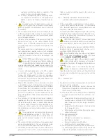
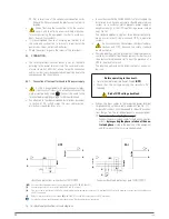
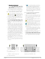
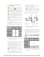
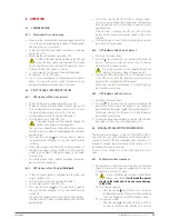
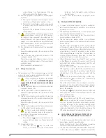
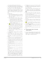
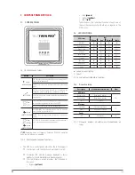
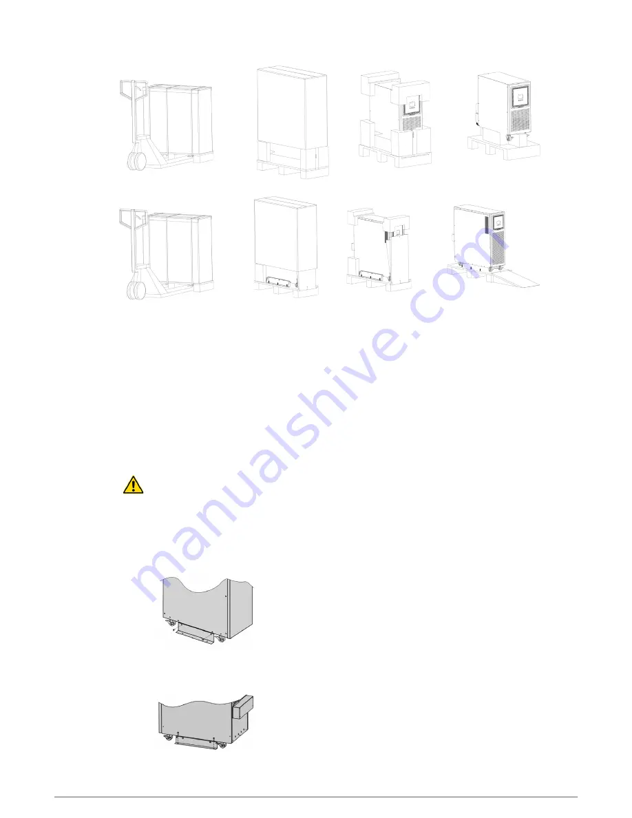
Fig. 4.
Fig. 5.
Fig. 6.
Fig. 7.
Fig. 8.
Fig. 9.
Fig. 10.
Fig. 11.
5.1.4. Transport till its location.
•
All the equipments have four casters (with mechanical
lock), so it is easy to move it till its right location once it
is unpacked.
Nevertheless, if the reception area is far from the installa-
tion location, it is recommended to move the UPS by means
of a pallet jack or the most suitable transport medium,
keeping in mind the distance between both points.
In case of long distances, it is recommended to move the
equipment with its packaging till the installation location
and finally unpack it there.
5.1.5. Location, immobilising and considerations.
5.1.5.1. Location for single units.
•
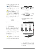
As an example, Fig. 14 shows the typical case depending
on the model. The equipment based on one single phase
(UPS with batteries fitted in) and UPS with the batteries in
a separate case or extended back up times.
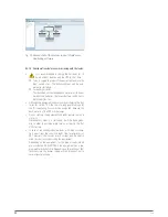
For a correct cooling, the space around the equipment
must be free of obstacles. Respect the minimum dis-
tances stated in Tab. 1 from section 1.2.1 of the docu-
ment EK266*08 (Safety Instructions), where the figures
of each dimension A, B, C and D are stated according to
the power rate of each equipment.
For the battery cases, keep the same distances as the
same UPS enclosure.
It is recommended to leave 75 cm additional free in each
side, for the possible tasks of the
(T.S.S.)
or the needed
power cable length to facilitate the movement of the
equipment to the front.
For extended back up times, with more than one case, it
is recommended to put one at each side of the equipment
and in case of a higher quantity proceed in the same way
alternately.
•
Equipments with three phase input TWIN/3 PRO2
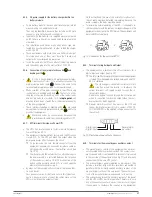
To unpack the equipment, follow the sequence of figures
8 to 10 (cut the wraps of the cardboard enclosure and
remove it from the top as it was a cover or in case of
wooden packaging use the needed tools; remove the
corners and plastic bag. The UPS will be naked over the
pallet.
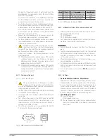
The equipment is fixed to the wooden pallet by means
of metallic support with «L» shape (stabilising support),
fixed at each side of the equipment.
Remove the screws that fix the equipment to the pallet
by means of the support [see Fig. 12 and 13].
Before downloading the equipment from the
pallet, the stabilising supports have to be removed
first, otherwise they will make difficult the downloading
procedure and they will be bent when impacting with
the wooden ramp, being able to cause damages to the
own structure of the equipment.
Put the ramp as figure 11 shows and download the
equipment from the pallet.
Fig. 12.
Fig. 13.
SLC TWIN PRO2
UNINTERRUPTIBLE POWER SUPPLY (UPS)
USER'S MANUAL


