19
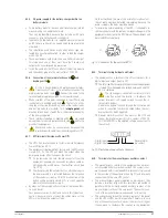
Connection to a three phase input:
Connect the power supply cables to the R, S T and N input
terminals,
by respecting the phase rotation of the
phases and neutral
stated in the labelling of the equip-
ment and this manual. Otherwise it can be damaged.
In case of discrepancies between the labelling and the in-
structions of this manual, the first ones will always prevail.
5.2.2. Connection of load/s to the output terminals or output 1.
•
As this is an equipment with protection against elec-
trical shocks of class I, it is essential to connect the
main protective earth cable [
]. Connect this cable to the
terminal before supplying voltage to the input terminals.
•
Pay attention to the «Recommended installation» document
in section 5.1.5.4., which states the cross cable section,
protection size and features, etc, ...
•
Connect the loads to the output power terminals or output
1, U and N,
by respecting the rotation of the phase and
neutral
stated in the labelling of the equipment and this
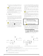
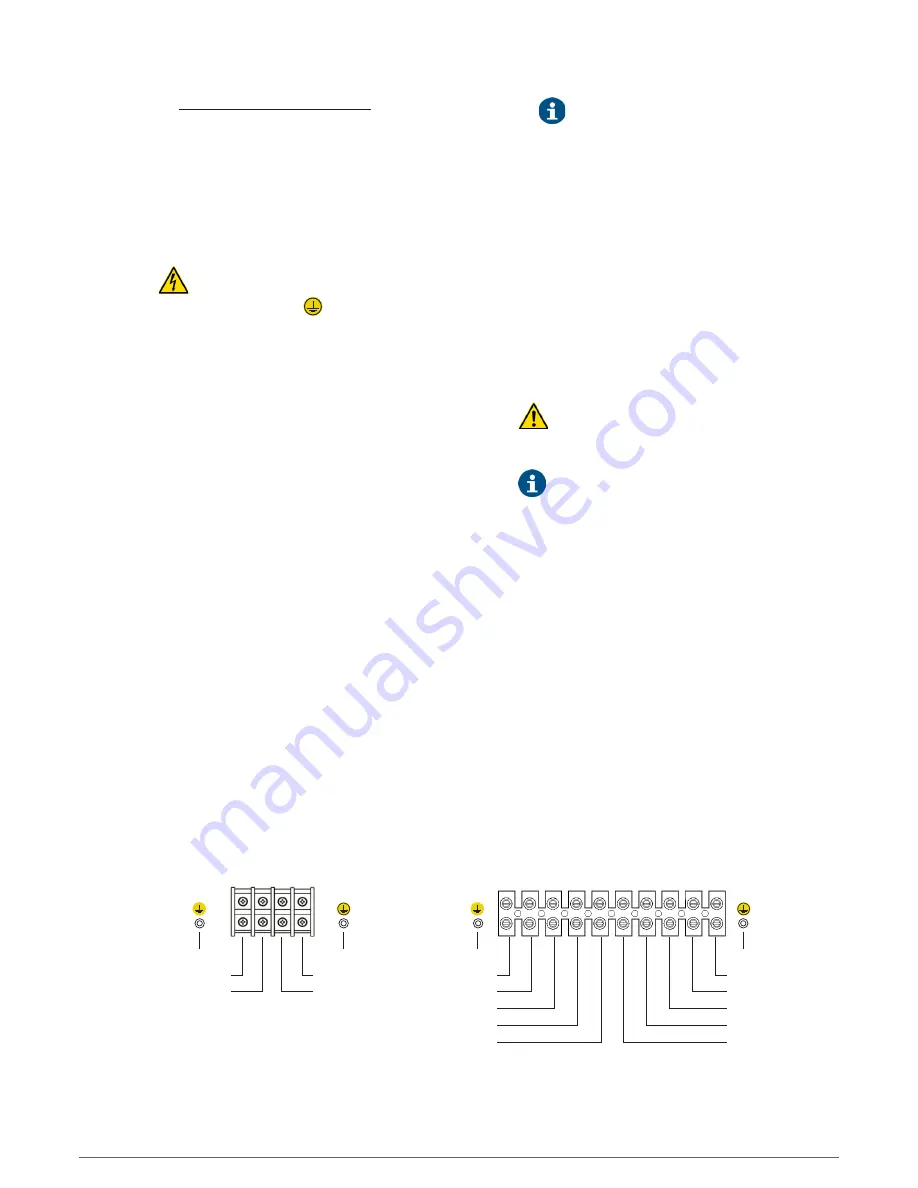
manual [see Fig. 17]. Otherwise the UPS and/or load/s can
be damaged.
•
For parallel systems, it will be needed to repeat the connec-
tions that go from the switchgear panel to each equipment.
In case of discrepancies between the labelling and the in-
structions of this manual, the first ones will always prevail.
•
As regards to the output protection to be fitted in the
switchgear or manual bypass panel, it is recommended to
split the output power into four different lines. Each one of
them will have a circuit breaker sized to the suitable figure.
This type of energy distribution at the output will allow that
in case of tripping one of them due to a problem in one of the
connected loads in that line, will not affect to the other ones.
Because the rest of loads will have their power supply con-
tinuously, because the only protection that will trip will be
the affected one by the short-circuit in their loads.
•
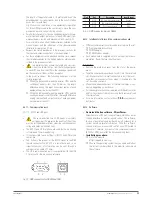
The single phase input equipments up to 10 kVA, apart from
the power terminal strip, also has two IEC outlets protected
by a 10 A breaker.
These outlets are connected in parallel with the output ter-
minals, so it is important to pay attention to the following
consideration:
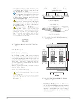
Bonding PE stud
U output phase
Output neutral
Main PE stud
Input neutral
R phase input
Bonding PE stud
U phase output 1
Output neutral 1
U phase output 2
Output neutral 2
(*)
+ Battery
Main PE stud
Input neutral
T input phase
S input phase
R input phase
– Battery
(*)
Regleta de bornes TWIN/3 PRO2 8.. 20 kVA
TWIN PRO2 4.. 10 kVA power terminal strip
(*)
No use terminals unless for B1 models, where an
external battery module is needed.
Fig. 17.
Power terminal strip.
The size of the output protection stated in the rec-
ommended installation document, is done for
the loads connected at the output power terminals.
This protection will be adapted by the fitter or end-user
to the installation in case part of the power is con-
nected to the IEC outlets, otherwise it is possible that
the input of the UPS will not trip, although the overload
alarm in the UPS is triggered.
5.2.3. Connection of the load/s to the output terminals 2
(TWIN/3 PRO2 from 8 to 20 kVA only).
•
Models from 8 to 20 kVA with three phase input has a
second set of output power terminals labelled as output
2, which supply voltage from the same source of output 1,
from the inverter or static bypass.
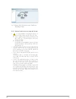
By means of the control panel the output 2 can be set as
Non-critical loads (set to «On»).
•
When setting the output 2 to Non-critical loads, the
back up time is reserved for the most critical loads,
which are connected to output 1, by breaking the power
supply of the output 2 during power outages.
•
The size of the output protection stated in the recom-
mended installation document, is the sum of both
output 1 and 2, which does not exceed the power rate of
the UPS in any case.
In case of using both terminal strips, the installer or
end-user will fit the suitable protection at each output,
otherwise the input protection of the equipment could
trip, apart from triggering the overload alarm.
•
In parallel systems check that the Output 2 is set to the
same figure in all of them, in order to avoid problems.
•
Connect the loads to the output power terminals 2, U and
N,
by respecting the rotation of the phase and neutral
stated in the labelling of the equipment and this manual [see
Fig. 17]. Otherwise the UPS and/or load/s can be damaged.
SLC TWIN PRO2
UNINTERRUPTIBLE POWER SUPPLY (UPS)
USER'S MANUAL


