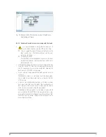
20
SALICRU
5.2.4. Connection with the external battery module and
extended back up times.
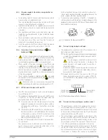
•
As this is an equipment with protection against elec-
trical shocks of class I, it is essential to connect the
main protective earth cable [
]. Connect this cable to the
terminal before supplying voltage to the input terminals.
•
Respect the instructions stated in this section and
those ones referred to the batteries in the EK266*08
safety instructions, section 1.2.3, because risk of electrical
shock exists, which can cause even the death.
•
Before starting the connection procedure between
the battery module or modules and the equipment,
check that the UPS input switch and the battery protection in
the module or modules are turned « Off».
•
The battery module has been designed for its equip-
ment. Do not modify the battery capacity or quantity
that makes it.
Also, it exists risk of electrical or electrocution shock due to
the high internal DC voltage, which can cause serious inju-
ries for the health and life.
•
Do not connect the battery modules between them or with
UPSs with different DC voltage (figure stated in the rear side
of each equipment).
•
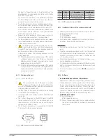
Tab. 3 states the physical connection between the UPS and
the battery module or modules.
Model
Batteries
(U
bat. block
x Nº) =
U
nominal
/ U
floating
Two poles switch
DC
voltage(V)
Current (A)
SLC-4000-TWIN PRO2
(12 V x 20) =
240 V / 275 V
440
20
SLC-5000-TWIN PRO2
25
SLC-6000-TWIN PRO2
32
SLC-8000-TWIN PRO2
40
SLC-10000-TWIN PRO2
50
SLC-8000-TWIN/3 PRO2
40
SLC-10000-TWIN/3 PRO2
50
SLC-15000-TWIN/3 PRO2
63
SLC-20000-TWIN/3 PRO2
100
Tab. 2.
Features of the protection to install in the battery
set belonging to the end-user.
•
All the standard UPSs include batteries in the same enclo-
sure, less those models called B0 and B1. For the standard
UPSs, the battery protection is done by internal fuses and
they are not accessible by the end-user.
Also, the battery modules have protection and in this case they
are doubled. Once are internal by means of fuses and not ac-
cessible by the end-user and the second ones by means of a
two poles circuit breaker or fuses
•
IMPORTANT FOR THE SAFETY: In case of installing the
batteries by yourself, the battery set must have a two
poles circuit breaker or fuses switch, with the size stated in
Tab. 2.
•
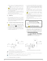
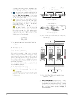
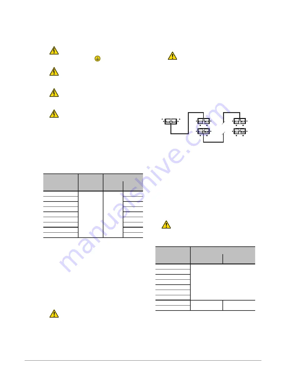
The connection of the UPS with the battery module will
be done with the supplied cable bundle. First connect one
cable end to the UPS terminals or connector and then the
other cable end to the battery module terminal or con-
nector. See Fig. 18, as an example.
Equipments with connectors, there is not any possi-
bility of wrong polarity connection.
For the equipments with terminals, respect the
polarity and the colour of the cables (red for
positive, black for negative and green-yellow for PE)
stated in the labelling of each module and this
manual.
•
When more than one battery module for the UPS is sup-
plied, the connection among them will be in parallel.
• • •
Connector at the
rear side of the UPS
Connectors at the rear side of the
battery modules
Battery
module 1
Battery
module
«
n
»
Fig. 18.
Example of connection between a UPS and bat-
teyr modules with connectors.
•
In extended back up times, to make easier the connection
between the UPS and the battery modules in parallel, all
the battery modules have two connectors or terminal strips.
•
Models with terminals, the polarity and colour of the cables
(red for positive and black for negative) must always be
respected.
•
Each battery module is totally independent for
each equipment.
It is completely prohibited to
connect two equipments to the same battery
module
.
Model
Connection mode with the batteries
In the UPS
In the external battery
module
SLC-4000-TWIN PRO2
Connector
SLC-5000-TWIN PRO2
SLC-6000-TWIN PRO2
SLC-8000-TWIN PRO2
SLC-10000-TWIN PRO2
SLC-8000-TWIN/3 PRO2
SLC-10000-TWIN/3 PRO2
SLC-15000-TWIN/3 PRO2
Terminal strip
Connector
SLC-20000-TWIN/3 PRO2
Tab. 3.
Connection between the UPS and battery module
or modules.


