21
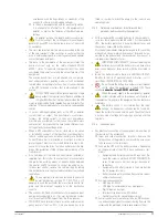
5.2.5. AC power supply for the battery charger built in the
battery module.
•
Some battery modules have an additional charger, which
means making some additional work.
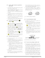
They can be identified, because they include an IEC male
connector, circuit breaker and cooling grid
•
Together with the module, it is supplied a power cord with
an IEC female connector in one end and Schuko plug in the
other end.
•
The installation must have a wall outlet, schuko type, pro-
tected by a circuit breaker of 6 A, in order to feed the charger
with 230 V AC.
•
Those equipments with more than one battery module of
this type, each one of them must have the Schuko wall
output with its corresponding protection.
•
Insert the cable into the IEC connector of the battery module
and the schuko plug into the wall outlet of 230 V AC.
5.2.6. Connection of the main protective earth
and
bonding earth
.
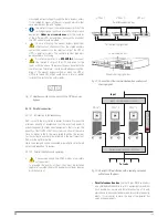
•
As this is an equipment with protection against elec-
trical shocks of class I, it is essential to connect the
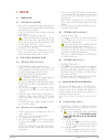
main protective earth cable [
]. Connect this cable to the
terminal before supplying voltage to the input terminals.
•
Make sure that all the loads connected to the UPS are only
connected to its bonding earth stud
. The fact of not lim-
iting the connection this bonding earth of the load or loads
and battery module or modules to this
single point
, will
break backfeed loops of earth that will decrease the quality
of the energy supplied.
•
Those terminals labelled as bonding earth
, are joined
among them to the main protective earth stud
and to the
ground of the equipment.
•
Never and under no circumstances disconnect the
protective earth cable from the building and/or UPS.
5.2.7. EPO terminals (Emergency Power Off).
•
The UPSs has two terminals to install a remote Emergency
Power Off button -EPO-.
•
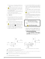
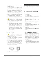
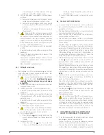
The equipment is delivered from factory with the EPO circuit
closed -NC-. So, the UPS will break the output when the
emergency power off button opens the circuit:
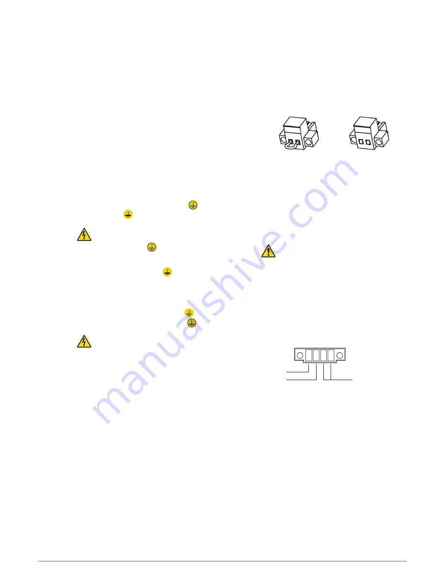
Or by removing the own female connector from the
equipment, because this connector includes a cable as
a bridge mode, which closes the electrical circuit [see
Fig. 19-A].
Or when pressing the external button, which belongs to
the end-user and it is installed between the terminals
of the connector [see Fig. 19-B]. The connection of the
button will be normally closed -NC-, so it will open the
electrical circuit when pressing it.
•
By means of the communication software, the inverse func-
tion can be set.
Less particular cases, it is better to not use this type of con-
nection, because in case of one of the cables were cut, the
EPO will not break the output voltage.
On the other hand, the use of the normally closed contact ,
the cut cable would be detected immediately, because the
power supply to the loads would be broken.
•
To restore the normal operating of the UPS, it is needed to in-
sert the connector with the cable as a bridge mode again in the
equipment or deactivate the EPO button. The equipment will
be turned ON automatically.
A
B
Fig. 19.
Connector for the external EPO.
5.2.8. Terminals for digital Input and Output.
•
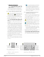
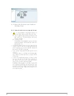
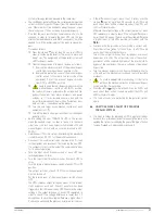
The equipment has a terminal strip of four terminals for a
digital input and output [see Fig. 20].
The «Start up-Shutdown» digital input. When the equipment
is turned ON, when applying a voltage between 5 and 12 V
DC, it is shutdown.
The static bypass is enabled from factory. In this
situation, when the inverter is shutdown the
output terminals will supply voltage through the in-
ternal static bypass.
Disable the bypass function through the control panel,
when it is required to break the output when the shut-
down order has been triggered.
General alarm dry contact. Any alarm of the UPS will
trigger the digital output (-NO- dry contact of 24V DC
1A). (ATTENTION to the applied voltage and current to
the contact).
– Digital input
+ Digital input
General alarm
dry contact
Fig. 20.
Digital input and output connector.
5.2.9. Terminals for the manual bypass auxiliary contact.
•
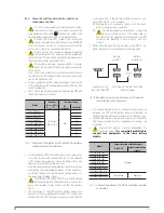
The manual bypass switch of the equipment has a micros-
witch located under its mechanical lock. This contact is nor-
mally opened and it is extended till a terminal strip located
in the rear side of the equipment [see Fig. 21] and internally
connected with the own UPS control.
•
The manual bypass panels supplied under request, they
include a terminal strip with two terminals connected in
parallel with the normally opened auxiliary contact of the
manual bypass switch of the own panel. The auxiliary con-
tacts of the manual bypass are advanced to its closing.
•
The connection between the auxiliary contact of the panel
and the UPS or UPSs must be in parallel. Therefore, in case
any of the auxiliary contacts closes the circuit will trigger
the command to shutdown the inverter, so the equipment
SLC TWIN PRO2
UNINTERRUPTIBLE POWER SUPPLY (UPS)
USER'S MANUAL


