22
SALICRU
will supply output voltage through the static bypass, unless
it is disabled by means of the control panel, which in that
case would break the load feeding.
•
In parallel systems, the manual bypass switch of the
switchgear panel will have a terminal strip for each
equipment.
Under no circumstances
joint the contacts
of the different UPSs among them, because the ground of
the UPS control would be joined.
•
In case of buying the manual bypass panel from
other sources, check that it has the stated auxiliary
contact and connect it to the terminal strip of the UPS or
UPSs in parallel systems. The auxiliary contact type must
be advanced to its closing.
•
As safety measures, it is
ESSENTIAL
, to connect
the terminals strips of the UPS, and even for the
loads, with the ones of the manual bypass panel with the
same function. Therefore, it will be avoided any wrong han-
dling of the manual bypass switch/es when the UPS or
UPSs are turned ON, which could cause a total or partial
failure of the installation and/or loads.
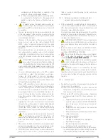
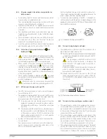
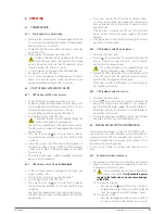
Fig. 21.
Auxiliary contact connector of the UPS manual
bypass.
5.2.10. Parallel connection.
5.2.10.1. Introduction to the redundancy.
N+X is usually the most reliable power structure. N means the
minimum quantity of equipments that the total load needs; X
means the quantity of redundant equipments, that is to say, the
quantity of faulty UPSs that the system can allow at the same
time. As higher is the X, the more reliable will be the system.
For those situations, where the reliability is the most important,
N+X will the optimal mode.
Up to 3 equipments can be connected in parallel to set a shared
output and redundant in power.
5.2.10.2. Parallel installation and operating.
•
The communication line -COM- means a low safety
voltage circuit.
To preserve the quality of them, they must be installed
separate from other lines with dangerous voltages (energy
distribution line).
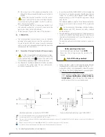
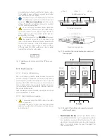
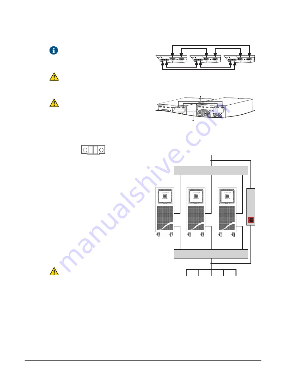
Parallel connection bus
Current sharing signal bus
UPS nr 1
UPS nr 3
UPS nr 2
Communication bus
Current sharing signal bus
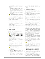
Fig. 22.
Connection of the communication bus and current
sharing signal.
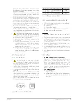
Input circuit breaker switches
Output circuit breaker switches
Man ual Bypass
SAI nº 1
SAI nº 2
SAI nº "3"
Input
To loads
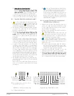
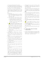
Fig. 23.
Parallel UPS installation with a switchgear panel
with manual bypass.
•
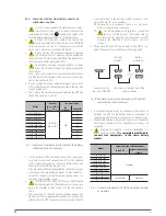
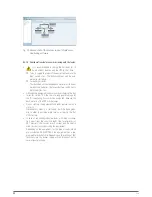
Parallel connection bus
. Use the 15 pins DB15 connectors
and shielded cable bundle to joint 3 equipments maximum.
Each bundle has a male and female connectors at its end,
which have to be connected between two correlative equip-
ments. It is essential to close the loop of the parallel bus
among the equipments.


