30
SALICRU
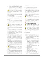
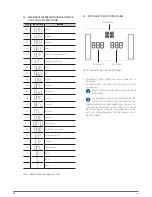
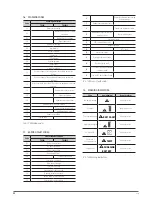
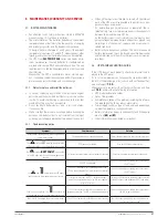
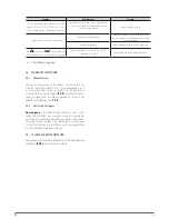
7.3. MEANING OF THE ABBREVIATIONS DISPLAYED IN
THE LCD OF THE CONTROL PANEL.
Code
LCD message
Meaning
ENA
A
U
E
Enabled.
DIS
d1S
Disabled.
ATO
AtO
Automatic.
BAT
bAt
Battery.
NCF
CF
U
Normal mode (not available for FC).
CF
CF
Frequency converter mode.
SUB
SUb
Down.
ADD
Add
Up.
ON
ON
Start up.
OFF
OFF
Shutdown.
FBD
Fbd
Not allowed.
OPN
OP
U
Allowed.
RES
RES
Reserved.
N.L
U
.
L
Neutral lost.
CHE
CHE
Checking.
OP.V
OP
.
U
Output voltage
PAR
PAR
Parallel, 001 is the first one.
EPO
EP
Emergency power off.
FR
FR
Frequency.
OPL
OPL
Load percentage.
R
R
Phase R.
S
S
Phase S.
T
T
Phase T.
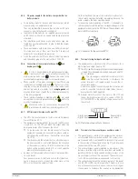
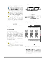
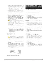
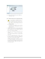
Tab. 9.
Abbreviations shown in the LCD.
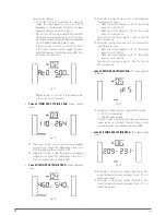
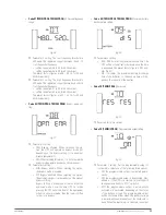
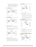
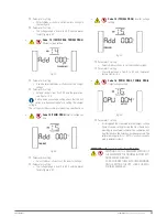
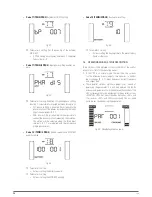
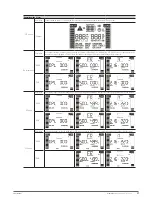
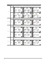
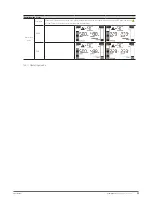
7.4. SETTINGS IN THE LCD CONTROL PANEL.
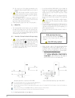
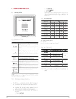
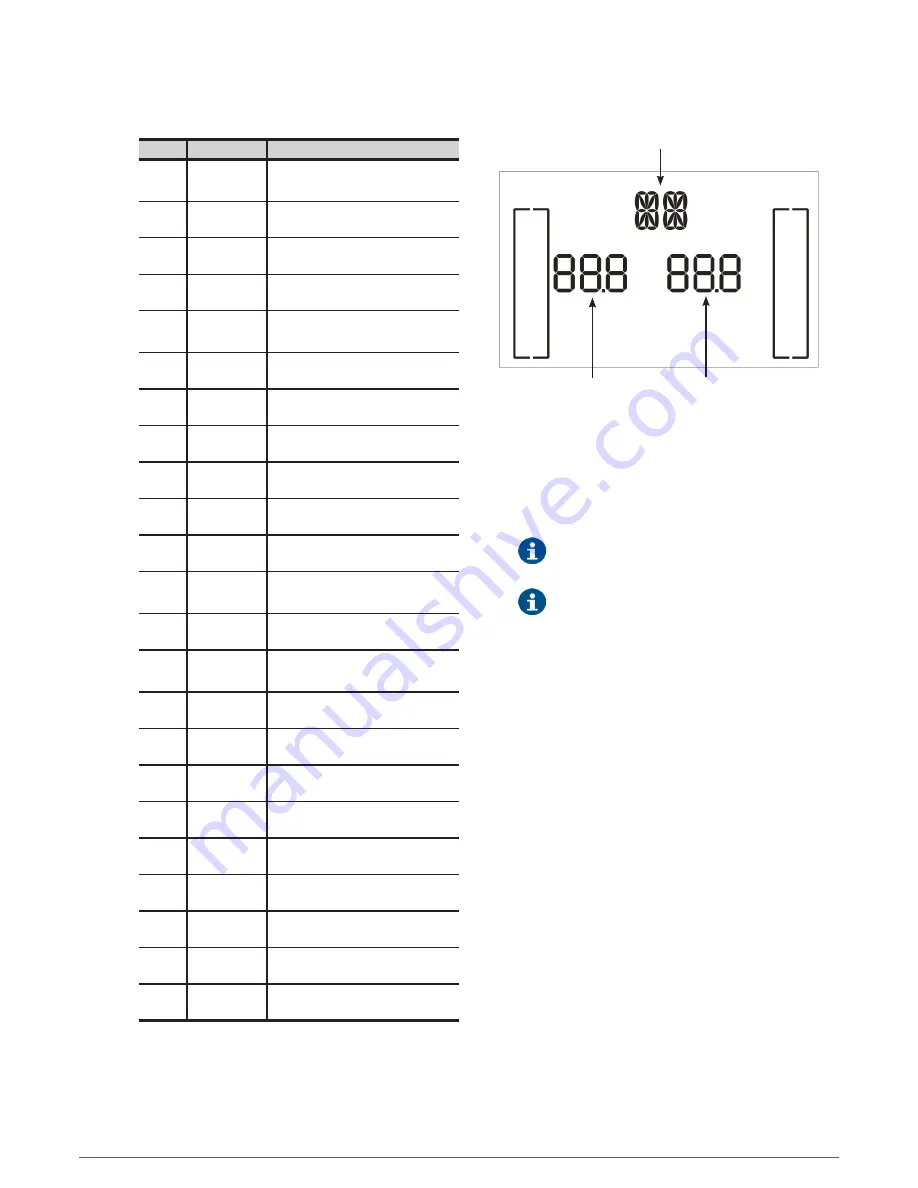
Parameter 1
Parameter 2
Parameter 3
Fig. 28.
Parameter layout in the LCD panel.
•
Parameter 1: Code of setting menu. Consult table 9 for its
description.
•
Parameter 2 and 3 are the options of the figures for each
setting menu.
Select the
«
Down
»
or
«
Up
»
keys to change the menu
or parameters.
Any parameter setting is only saved when the UPS
is shutdown on normal mode and internal or ex-
ternal batteries are connected, depending on the case. (It is
understood as shutdown on normal mode to turn off the
input circuit breaker switch when the equipment is on by-
pass or no voltage -depending if the static bypass is ena-
bled or disabled-).


