36
SALICRU
•
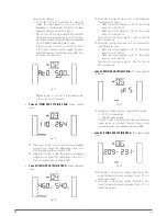
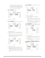
Code 17
(TWIN PRO2)
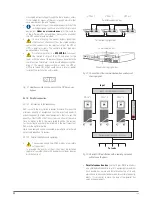
. External MOD BAT setting.
Fig. 51.
Parameter 3 setting: Set the quantity of the external
MOD BAT.
–
0-7: The setting allow figures between 0-7. The preset
factory figure is 0
•
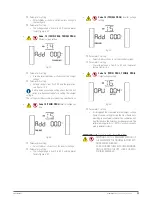
Code 17
(TWIN/3 PRO2)
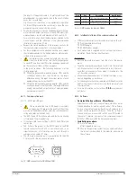
. Input phase shifting enable / dis-
able.
Fig. 52.
Parameter 3 setting: Enabling / Disabling phase shifting
function. It is possible to selected between two options:
–
DIS: phase shifting is disabled. Pay attention to the
phase rotation of the phases by respecting the label-
ling of the equipment -R, S, T-.
–
ENA: phase shifting is enabled. It makes possible to
connect the phases without respecting their rotation.
This option will be selected, when the three input
terminals -R, S, T- are supplied with the same phase
(single phase mains).
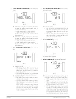
•
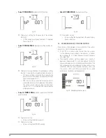
Code 18
(TWIN/3 PRO2)
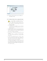
. Battery capacity and MOD BAT
quantity setting.
Fig. 53.
Parameter 2 setting.
–
It allows setting the battery capacity.
Parameter 3 setting:
–
It allows setting the MOD BAT quantity.
•
Code 19
(TWIN/3 PRO2)
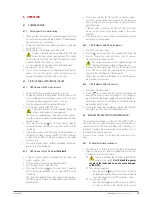
. Back up time setting.
Fig. 54.
Parameter 3 setting:
–
It allows setting the back up time to the preset factory
figure or other ones.
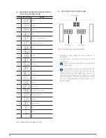
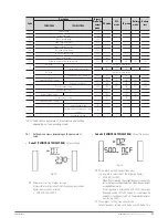
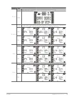
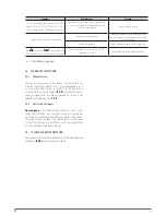
7.5. OPERATING MODES / STATUS DESCRIPTION.
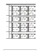
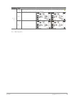
Table 10 shows the displayed screens in the LCD of the control
panel [status] for all the operating modes.
1.
If the UPS is on normal mode, there will be five screens
for the following measurements: three phases to neutral
input voltages [R, S, T], input frequency, output frequency
and output load.
2.
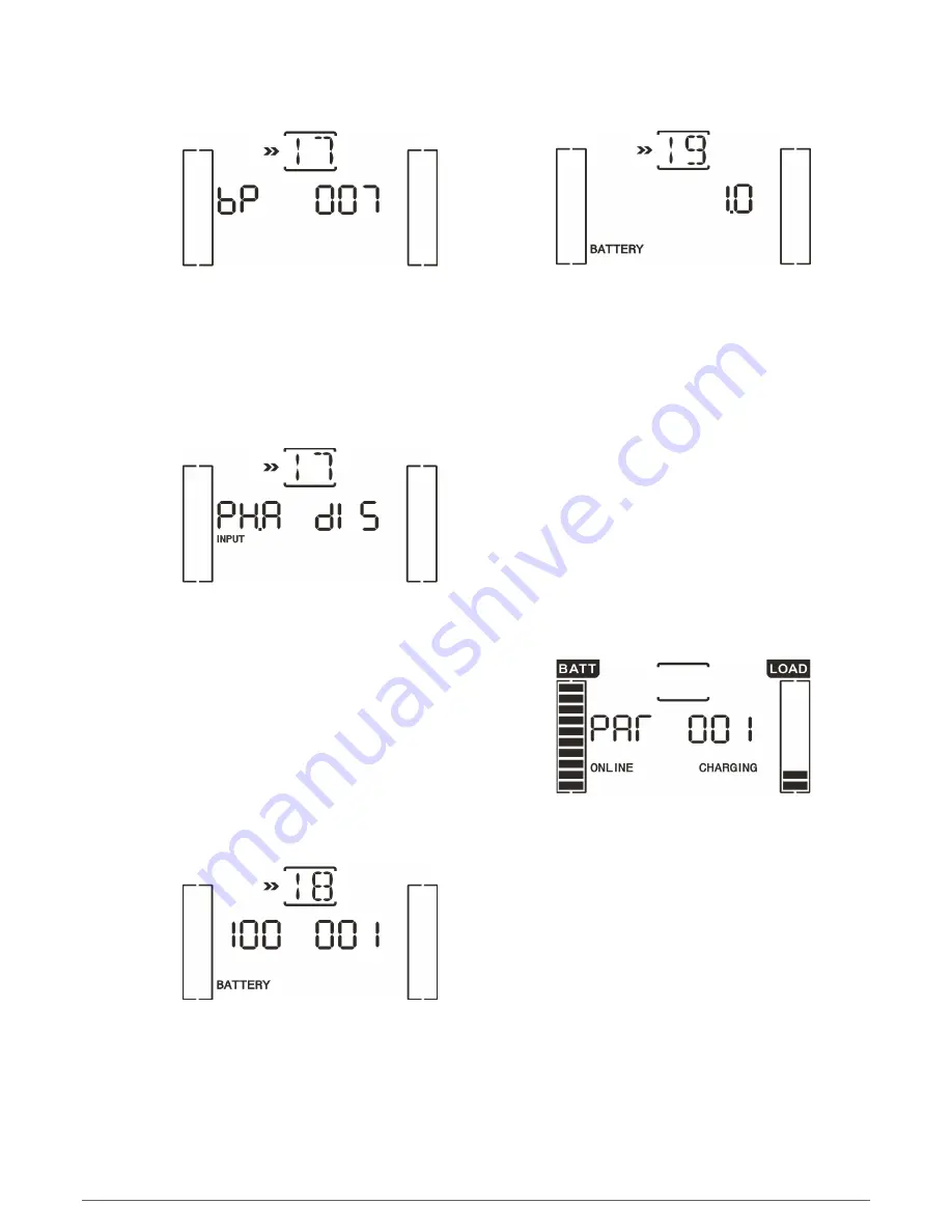
Those parallel systems, which are properly set, instead of
displaying the parameter 2, it will be displayed the «PAR
»
acronym and parameter 3 will be displayed the number of the
UPS corresponding to the equipment in the parallel system.
«MASTER
»
UPSs will be assigned by default as «001
»
and
the slaves as «002
»
and «003
» respectively
. The assigned
numbers can change during their operation.
Fig. 55.
Parallel system screen.

