background image

13

INSTALLATION

SALICRU

5.7.1.2.  1500 / 2000 VA models

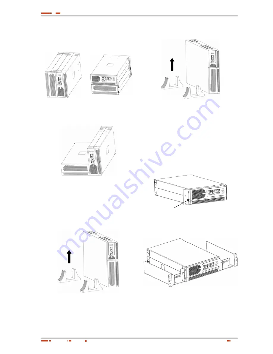
UPS and Battery modules integrate into three types of 
tower forms:


Tower form 1  

Tower form 2

Fig. 16. 

Integrated format views 1 and 2 UPS - Bat-

teries


Tower form 3

Fig. 17. 

Integrated format view 3 UPS - Batteries

5.7.1.3.  3000 VA model

Follow the next steps for setup:

1. 

Slide down the UPS vertically and put two UPS stands 
at the end of the tower.

Fig. 18. 

View of the setup first step

2. 

Place the UPS into two stands carefully.

Fig. 19. 

UPS placed in his stands

5.7.2.  Rack-Mount Setup

750/1000/1500/2000 VA (optional) and 3000 VA can be in-
stalled in 19” racks. And the UPS and external battery en-
closure need 2U of valuable rack space.  Use the following 
procedure to install UPS in a rack. 

5.7.2.1.  750 / 1000 VA models (optional)  

1. 

Align the mounting ears with screw holes on the side 
of the UPS.

Fig. 20. 

Placement lateral stands

2. 

Install rack-mounting rails with the screws provided 
tightened up into rack enclosure.

Fig. 21. 

Install rack-mounting rails

Summary of Contents for 750 VA

Page 1: ...H T I N G F L O W D I M M E R S TA B I L I Z E R S P O W E R S U P P LY S TAT I C I N V E R T E R S P H O T O V O LTA I C I N V E R T E R S M I C R O T U R B I N E S V O LTA G E S TA B I L I S E R S...

Page 2: ......

Page 3: ...Start function 5 6 Turn On Off 5 7 UPS Setup 5 7 1 Tower Setup 5 7 2 Rack Mount Setup 5 8 Emergency Power Off E P O set up 5 9 Additional battery installation setup 5 9 1 1500 2000 VA models 5 9 2 300...

Page 4: ...electrical discharge symbol Pay special attention to it both in the indication on the equipment and in the paragraph referred to this user s manual i Main protective earthing terminal symbol Con nect...

Page 5: ...uality Assurance The marking shows the conformity to the EEC Directive quoted between brackets by means of the application of the following standards 2006 95 EC of Safety of Low Voltage 2004 108 EC of...

Page 6: ...ite Wiring Fault Battery Fault Self Test Failure A push button from the front panel allows silencing of the AC fail alarm and the initiation of the UPS self test sequence as well The UPS case for 750...

Page 7: ...tep 1 By entering the CNFG button more than three seconds UPS will transfer to Rated voltage configure mode Step 2 Pressing the CNFG button more than one second the UPS allows you to select the Rated...

Page 8: ...he type of failure Battery bad When the battery of the UPS is bad the symbol will be displayed constantly Over load time out When UPS is Over load time out the symbol will be dis played constantly At...

Page 9: ...UPS is overload Steady UPS is overload and the time is out Steady UPS is overload and the time is out Steady UPS is plugged intro an improperly polarity only for LV models Steady Battery bad Code 1 Ba...

Page 10: ...em Network Surge Protection 2 RS232 Dry Contact Communication Port 3 USB Communication Port 4 AC Input Power cord AC Input Protection 5 AC Output NEMA AC Output IEC Table 3 Rear panel description for...

Page 11: ...table 4 4 2 2 Battery module Fig 11 Rear panel for HV model Fig 12 Rear panel for LV model 4 4 3 3000 VA model Fig 13 Rear panel for HV model Fig 14 Rear panel for LV model No Function LV model 110 1...

Page 12: ...connection Connect one load related device to each of the power re ceptacles supplied at the rear of the UPS 5 4 Modem Phoneline Connection Plug incoming telephone line into the In socket at the back...

Page 13: ...Fig 18 View of the setup first step 2 Place the UPS into two stands carefully Fig 19 UPS placed in his stands 5 7 2 Rack Mount Setup 750 1000 1500 2000 VA optional and 3000 VA can be in stalled in 19...

Page 14: ...side of the UPS is facing to you b 2 Disconnect the cable from the UPS and Battery modules Fig 24 UPS and Battery are disconnected c Loosen the screws and remove the UPS and Bat tery modules cover fro...

Page 15: ...ff then plug all loads into the output receptacle properly protected by a circuit breaker of fuse in accordance with national and local electrical codes Fig 33 3000 VA model in 19 rack 5 8 Emergency P...

Page 16: ...tional battery connection 5 9 1 2 Additional battery connection in tower form Fig 35 Rear view of the additional battery connection 5 9 2 3000 VA model There is one external battery port for the UPS i...

Page 17: ...owing table and diagram shows the pin out of fe male DB9 connector and its function Do not apply values higher than 24 V DC and 1 A to the pins of the AS400 connector Pin Description E S 1 UPS failure...

Page 18: ...e UPS may be failed Contact local dealer The UPS is beeping continuously The UPS is in fault condition Check the audible alarms condition table Buttons does not work The UPS is in green mode Wait for...

Page 19: ...screw up the battery retaining battery bracket 6 Close and reinstall the front panel 6 2 2 1500 2000 VA models 1 Remove the battery case front panel by pulling on both ends Fig 40 Front panel removal...

Page 20: ...uct inside the war ranty period repairs to our facilities at no cost the faulty part or parts The transport expenses and packaging will be borne to the user Guarantee for period time higher than 10 ye...

Page 21: ...time inside the same day or as maximum in the next 24 hours of the fault notification LS14HLS Customer s attention from Monday to Saturday from 6 h to 20 h Response time is inside the same day or as m...

Page 22: ...Line Mode 110 0 8 shutdown after 3 minutes 150 0 10 shutdown after 10 cycles Battery Mode 110 6 shutdown afters 30 seconds 120 6 shutdown after 5 cycles TRANSFER TIME Typical 2 4 ms typical 6 ms max...

Page 23: ......

Page 24: ...AINE ARGENTINA BRAZIL CHILE COLOMBIA CUBA ECUADOR PERU URUGUAY VENEZUELA SAUDI ARABIA ALGERIA EGYPT JORDAN KUWAIT MOROCCO TUNISIA KAZAKHSTAN PAKISTAN UEA PHILIPPINES INDONESIA MALAYSIA THAILAND VIETNA...

Reviews: