14
INSTALLATION
3.
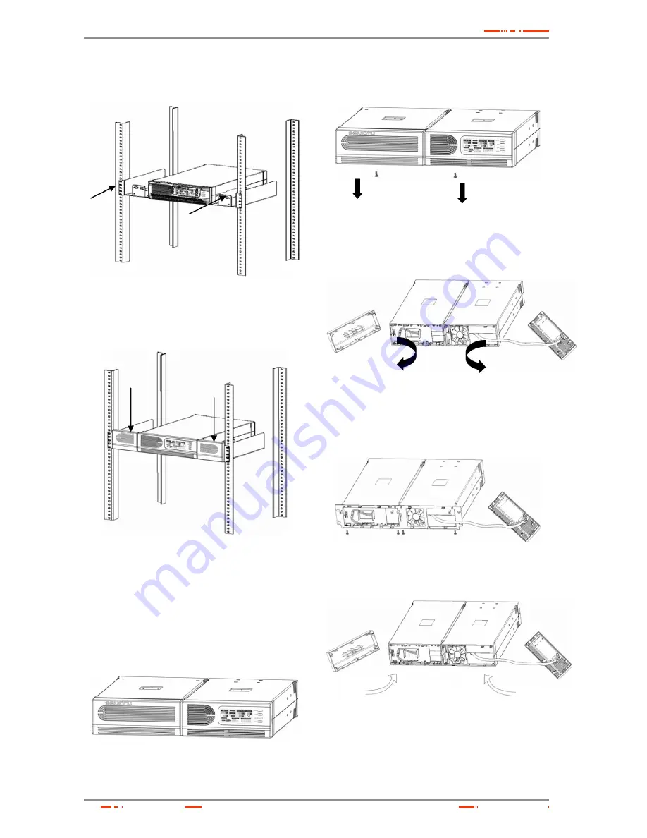
Insert UPS into the slide assemblies and lock it in the
rack enclosure.
Fig. 22.
Attaching the UPS in the rack cabinet
4.
Add up the front panels for both sides. The load can
be connected.
Fig. 23.
End of the installation
5.7.2.2. 1500 / 2000 VA models (optional)
1.
UPS and Battery integrate into a rack form:
a.
Place the UPS on a flat and in a clean place that
the front side of the UPS is facing to you.
b.
2. Disconnect the cable from the UPS and Battery
modules. .
Fig. 24.
UPS and Battery are disconnected
c.
Loosen the screws and remove the UPS and Bat-
tery modules cover from the unit.
Fig. 25.
Removal of screws and covers
d.
Pull two covers toward the direction shown as
below.
Fig. 26.
Removing covers
e.
Align the mounting bracket with the screw holes
on the each side of UPS and Battery modules and
secure with the supplied screws.
Fig. 27.
Align the mounting bracket
f.
Reinstall the UPS and Battery modules cover.
Fig. 28.
Covers reinstallation
USER'S MANUAL


