34
SALICRU
10. OPERATIONS
The components that can only be accessed by opening the
protective cover with tools cannot be operated by user. Only
qualified service personnel are authorized to remove such
covers.
10.1. INTRODUCTION
The Modular UPS rack system provides the critical load (such
as communication and data processing equipment) with high
quality uninterruptible AC power. The power from the UPS is
free from voltage and frequency variations and disturbances
(interruption and spike) experienced at the Mains AC input
supply.
This is achieved through high frequency double conversion
power pulse width modulation (PWM) associated with fully
digital signal processing control (DSP), which features high
reliability and convenience for use.
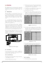
As shown in fig. 49, the AC input mains source is supplied at
UPS input and converted into a DC source. This DC source feeds
the Inverter that converts the DC source into a clean and input
independent AC source. The battery powers the load through
the inverter in case of an AC input mains power failure. The
utility source can also power the load through the static bypass.
When the UPS needs maintenance or repair, the load can be
transferred to maintenance bypass without interruption and
the power module and bypass module can be removed for
maintenance.
REC
INV
BAT
CHARGER
REC
INV
BAT
CHARGER
BCB
Battery Module
BCB
bA
bB
bC
mA
mB
mC
mN
Batt+
BattN
Batt-
oA
oB
oC
oN
Power Module 1#
Power Module 10#
Bypass Module
Maintenance Bypass
Fig. 49.
Single Unit Block Diagram
10.2. UPS STARTUP
Do not start the UPS until the installation is completed, the
system has been commissioned by authorized personnel and
the external power isolators are closed.
10.2.1. Start-Up Procedure
This procedure must be followed when turning on the UPS from
a fully powered down condition.
The operating procedures are as follows:
1.
Open the external power switch. Open the internal power
switch. Open the UPS door, connect the power supply
cables and ensure the correct phase rotation.
2.
Close the output circuit breaker (Q3). Close the mains input
circuit breaker (Q1) and connect the mains power.
3.
The LCD starts up at this time.
4.
The Rectifier indicator flashes during the startup of
rectifier. The rectifier enters normal operation state, and
after about 20s, the rectifier indicator goes steady green.
After initialization, the bypass static switch closes.
LED
Status
Rectifier indicator
Green
Battery indicator
Red
Bypass indicator
Green
Inverter Indicator
Off
Load indicator
Green
Status indicator
Green
Table 21.
Inverter start up
5.
The inverter starts up automatically. The inverter indicator
flashes during the startup of inverter. After about 1minute,
the inverter is ready, the UPS transfers from bypass to
inverter, the bypass indicator turns off, and the inverter and
load indicators turn on.
LED
Status
Rectifier indicator
Green
Battery indicator
Red
Bypass indicator
Off
Inverter Indicator
Green
Load indicator
Green
Status indicator
Green
Table 22.
Nornal mode
6.
Close external battery switch, battery indicator turns off, a
few minutes later, the battery will be charged by UPS.
LED
Status
Rectifier indicator
Green
Battery indicator
Green
Bypass indicator
Off
Inverter Indicator
Green
Load indicator
Green
Status indicator
Green
Table 23.
Battery charged
10.2.2.
Battery Start
1.
Verify that the battery is properly connected.


