17
4.3. GENERAL DESCRIPTION.
The
SLC ADAPT
series is classified as an on-line double-
conversion uninterruptible power supply with DSP control and
three-level IGBT inverter technology, modular topology and
great flexibility.
Reliability
: The DSP control associated with three-level PWM
technology increases the performance of the system and, together
with the redundancy of the modules, manages to increase the
availability of power to the critical loads, a parameter that
contributes to achieving a good TIER classification for the entire
system.
Availability
: Its hot-swap modules can be added or replaced
during operation, thereby improving mean time to repair
(MTTR) and reducing maintenance costs. Moreover, both the
control display and the bypass module can be replaced without
affecting the operation of the device. In addition, the sys-
tem’s remote management, which can be integrated into any
platform, also makes operation easier. The extensive backup
options available, along with smart battery charging, ensure
continuous operation of the protected critical loads.
Modularity
: This allows simple configurable solutions from
30 to 1500 kVA by installing 30 or 50 kVA modules in the 6-slot
(30 kVA modules) or 10-slot cabinets. As composite solutions,
a maximum of 30 modules can be paralleled to obtain higher
power systems or N+n structures. Either way, it is only possible
to install identical modules in the same cabinet and/or parallel
cabinets with modules of equal power. This enables gradual
growth and scaling for future expansion depending on the
need for pay-as-you-grow protection, improving the total cost
of ownership (TCO) and providing a high level of flexibility. At
operational level, a cabinet consisting of ‘N’ modules connected
in parallel is considered a single UPS.
Any expansion or structural change to the number of modules
is possible even during normal operation and without needing
to shut down the hot-swappable system, all with the simple
use of a screwdriver to remove or screw the fixing screws of
the module(s). Although all of the UPS’s modules incorporate a
battery charger that can allocate up to 20% of its rated power
to maintaining them at an optimum charge level depending on
the type and number of elements, 50 A battery charger modules
are available to be installed solely with the 30 kVA SLC ADAPT
modules. As many charging modules as considered appropriate
can be installed, but this will be to the detriment of the total
number of UPS modules and, consequently, the total power of
the system, which will be reduced.
Backup
: The capacity of the batteries determines the backup
time of the system when replacing the usual source of energy
during mains failures. The accumulator bank is always common
to any system mounted in the same cabinet. Batteries owned by
the customer or supplied with the UPS, depending on different
factors in addition to the power and/or backup requested, can
be installed in a back or one or more cabinets, always external
to the UPS itself.
4.3.1. Introduction.
SLC ADAPT
series UPSs basically consist of:
•
6- or 10-slot cabinet to install the power modules.
•
Power modules consisting of the following blocks:
AC/DC PFC rectifier.
Battery charger.
DC/AC inverter.
Digital control and UPS management.
•
Centralised bypass module: control of UPS and parallel pa-
rameters.
•
Maintenance bypass.
•
Control panel with touch screen (see section X for more
information).
•
Batteries (number, type and location depending on the
backup time).
•
Self-supporting 36 and 46U cabinets for the placement of
the different modules.
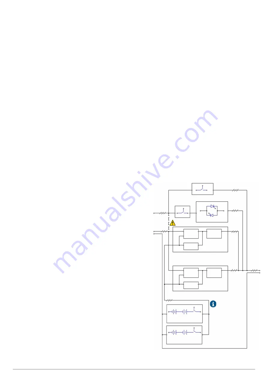
4.3.2. Conceptual diagram of the system.
The modular UPSs of the
SLC ADAPT
series consist of power
modules, a bypass and monitoring module, and a cabinet with
a range of disconnectors for Input, Bypass Output and Manual
Bypass. The 180 and 300 kVA UPSs only have a manual bypass
switch. One or more battery branches should be installed to
provide backup power in the event of a power failure. The
structure of the UPS is shown in Fig. 14.
STATIC BYPASS MODULE
DC / AC
INVERTER
MANUAL BYPASS
REC / PFC
BAT / DC
DC / DC
INVERTER
BYPASS
STATIC BYPASS
LINE INPUT -R, S, T-
N
POWER MODULE # 1
DC / AC
INVERTER
REC / PFC
BAT / DC
DC / DC
INVERTER
POWER MODULE #N
•
•
•
OUTPUT
U, V, W
N
BATTERY MODULE
BCB
BATTERY MODULE
BCB
Connection strips
between phases for mains.
Q1
Q2
INLET LINE OF UPS
-R, S, T-
The batteries are represented in
the structural diagram as they are
an essential part of all UPSs,
although they will never be
included in the cabinet itself. The
batteries can be supplied in a
separate cabinet, in a bank or not
supplied if the customer already
has them.
Fig. 14.
Conceptual diagram of the SLC ADAPT series
modular UPS.
SLC ADAPT
UNINTERRUPTIBLE POWER SUPPLY (UPS)
USER'S MANUAL
Summary of Contents for SLC ADAPT Series
Page 1: ...SLC serie ADAPT 180 300 y 500 kVA UNINTERRUPTIBLE POWER SUPPLY UPS USER S MANUAL...
Page 12: ...12 SALICRU Fig 8 Front view of 10 slot cabinet 500 kVA 300 kVA at 3x208 V with closed doors...
Page 64: ...64 SALICRU...
Page 65: ...65 SLC ADAPT UNINTERRUPTIBLE POWER SUPPLY UPS USER S MANUAL...


