33
Port
Name
Function
J4-1
EPO_NC
EPO activation when disconnecting from
J4-2
J4-2
+24 V
+24 V
J4-3
+24 V
+24 V
J4-4
EPO_NO
EPO activation when connecting to J4-3
Tab. 9.
Description of the input port for remote EPO.
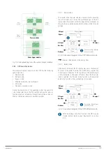
Relay interface of the generator
The default function of J5 is the interface for the generator. The
connection of pin 2 of J5 with a +24 V power supply indicates
that the generator has been connected to the system. The
diagram of port J5 is shown in Fig. 43 and the description in
Tab. 7.
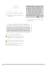
J5
GEN
+24V
AUX-N.O.
AUX-N.O.
Generator
Generator
+24V_DRY
GEN_CONNECTED
Fig. 43.
Connection diagram of the connection port of the
generator and interface status.
Port
Name
Function
J5-1
+24 V_DRY
+24 V
J5-2
EXTER_BYPASS
‘NO’ auxiliary contact of external manual
bypass switch
J5-3
GND
Common
Tab. 10.
Description of the interface status and generator
connection.
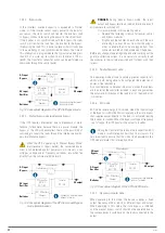
Input port of the BCB
The default function of J6 and J7 is that of being the ports
of the BCB. A diagram of the ports is shown in Fig. 44 and a
description in Tab. 7.
B C
B
_ D R
V
B C
B
_ C O
N
T
J6
J7
B C
B
_ O N
L
+24V
+24V
+24V
BCB_ DRIV
BCB_ ST
ATUS
BCB_ ONL
J6
J7
+24V
+24V
+24V
GND_ DRY
Fig. 44.
Connection diagrams of the ports of the BCB.
Port
Name
Function
J6-1
BCB_DRV
It provides a pulse signal of +24 V / 20 mA for
the remote control of the battery circuit breaker
through its coil. This signal activates the ‘Off’
switch
J6-2
BCB_CONT
Status of the BCB switch. Its normally closed
(‘NC’) auxiliary contact can be connected
between this pin and the GND
J7-1
GND
+ 24 V ground reference
J7-2
BCB_ONL
Not useful. Not implemented
Tab. 11.
Description of the BCB port.
In the default configuration, when using a circuit breaker
with auxiliary contacts with J6-2 and J7-1 connected to
auxiliary contact terminals to obtain the status of the BCB, this
function must be enabled by short circuiting J7-1 and J7-2.
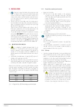
Output relay interface for battery warnings
The default function of port J8 is to present battery under-
voltage or overvoltage warnings. When the battery voltage
is lower than the programmed value, an auxiliary signal from
the relay interface will be activated. A diagram of the ports is
shown in Fig. 45 and a description in Tab. 7.
BA
T_LOW_ALARM_NC
BA
T_LOW_ALARM_NO
BA
T_LOW_ALARM_GND
J8
Fig. 45.
Diagram of the relay interface of battery warnings.
Port
Name
Function
J8-1
BYP_ALM_NC
Normally closed (NC) contact, STATIC BYPASS
relay interface signal
J8-2
BYP_ALM_NO
Normally open (NO) contact, STATIC BYPASS
relay interface signal
J8-3
GND
Common for STATIC BYPASS relay interface
signal
Tab. 12.
Description of the relay interface of battery
warnings.
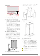
Relay interface of general output alarms
The default function of port J9 is to present general alarm
warnings. When one or more warnings are triggered, an
auxiliary relay interface signal will be activated. A diagram of
the ports is shown in Fig. 46 and a description in Tab. 7.
SLC ADAPT
UNINTERRUPTIBLE POWER SUPPLY (UPS)
USER'S MANUAL
Summary of Contents for SLC ADAPT Series
Page 1: ...SLC serie ADAPT 180 300 y 500 kVA UNINTERRUPTIBLE POWER SUPPLY UPS USER S MANUAL...
Page 12: ...12 SALICRU Fig 8 Front view of 10 slot cabinet 500 kVA 300 kVA at 3x208 V with closed doors...
Page 64: ...64 SALICRU...
Page 65: ...65 SLC ADAPT UNINTERRUPTIBLE POWER SUPPLY UPS USER S MANUAL...

