37
2.
The inverter and status LED indicators turn off, the alarm
is activated and the inverter stops. The bypass supplies
power to the loads.
3.
Open the external battery circuit breaker and close the
maintenance bypass circuit breaker. The load is powered
through the maintenance bypass and static bypass.
4.
For 180 and 300 kVA devices:
The maintenance bypass
supplies power to the loads.
5.
For 500 kVA devices:
The maintenance bypass supplies
power to the loads.
One by one, open the input circuit breaker (Q1), bypass
input circuit breaker (Q4) and, finally, the output circuit
breaker (Q3). The system will shut down.
Before performing this operation, read the messages that
appear on the LCD. Make sure that the power of the
bypass is correct and that the inverter is synchronised to
avoid the risk of interrupting power to the load.
DANGER!
If it is necessary to carry out maintenance on the
power unit, wait 10 minutes for the DC bus capacitor to
completely discharge before removing the cover.
6.3.5. Transfer from maintenance Bypass mode to Normal
mode.
The following procedure is used to transfer the load from
maintenance bypass to the output of the inverter.
For 180 and 300 kVA devices
1.
Power the UPS with the Bypass input voltage. The static
bypass connects 30 seconds after the display illuminates and
the green bypass LED activates. The load is then powered
through the maintenance bypass and the static bypass.
2.
Open the circuit breaker of the maintenance bypass so that
the load can be powered through the static bypass. The
rectifier and inverter start.
3.
After 60 seconds, the system transfers to Normal mode.
For 500 kVA devices
1.
Close the output circuit breaker (Q3), then close the input
circuit breaker (Q1) and finally close the bypass input circuit
breaker (Q4). The system will start up.
1.
The static bypass connects 30 seconds after the display
illuminates and the green bypass LED activates. The load
is then powered through the maintenance bypass and the
static bypass.
2.
Close the external battery circuit breaker.
3.
Open the circuit breaker of the maintenance bypass so that
the load can be powered through the static bypass.
4.
After 30 seconds, the rectifier starts, the rectifier LED is
green and the inverter starts.
5.
After 60 seconds, the system transfers to Normal mode.
6.4. BATTERY MAINTENANCE.
If the batteries have not been used for a long period of time, it
is necessary to verify their condition. There are two methods to
carry out this verification:
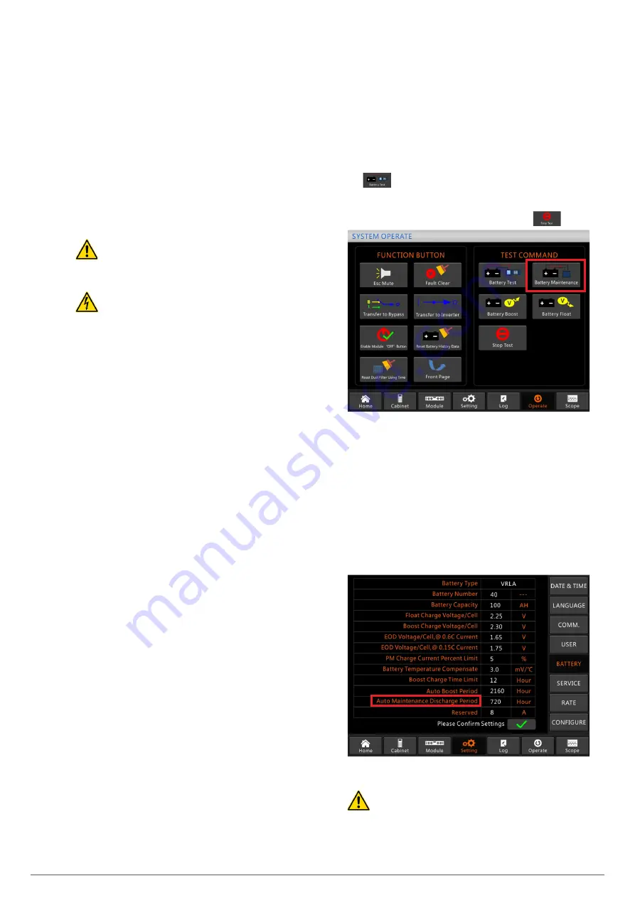
1.
Manual discharge
. Enter the Operation menu, as shown
in Fig. 52, by clicking on the ‘Battery Maintenance’ icon
the system transfers to battery mode to start the
discharge, stopping when the batteries reach 20% of ca-
pacity or there is an undervoltage. The user can stop the
discharge by clicking on the ‘Stop Test’ icon
.
Fig. 52.
Battery maintenance.
2.
Automatic discharge
. The system performs an automatic
battery test once the settings are completed. The settings
procedure is as follows:
a.
Enable automatic battery discharge through the ‘Con-
figure’ option in the settings menu. Select ‘Automatic
battery discharge’ and confirm (factory configuration).
b.
Period setting for automatic battery discharge. Select
the ‘Battery’ option in the settings menu (see Fig. 53).
Set the time period to ‘Auto Maintenance Discharge
Period’ and confirm.
Fig. 53.
Automatic battery discharge period setting.
The charge required for automatic maintenance discharge
must be between 20 and 100%. Otherwise, the system
will not start the process automatically.
SLC ADAPT
UNINTERRUPTIBLE POWER SUPPLY (UPS)
USER'S MANUAL
Summary of Contents for SLC ADAPT Series
Page 1: ...SLC serie ADAPT 180 300 y 500 kVA UNINTERRUPTIBLE POWER SUPPLY UPS USER S MANUAL...
Page 12: ...12 SALICRU Fig 8 Front view of 10 slot cabinet 500 kVA 300 kVA at 3x208 V with closed doors...
Page 64: ...64 SALICRU...
Page 65: ...65 SLC ADAPT UNINTERRUPTIBLE POWER SUPPLY UPS USER S MANUAL...

