38
SALICRU
6.5. EPO.
The EPO button is located on the control panel and has the
function of turning off the UPS in emergency conditions (e.g.,
fire, flood, etc.). The EPO button has a protection to prevent
accidental activation, see Fig. 54.
When the button is pressed, the system will turn off the rectifier
and inverter, stop powering the load immediately (including
the inverter and bypass) and the battery will stop charging or
discharging.
If there is an input mains, the UPS’s control circuit will continue
to be activated but the output will turn off. To completely
isolate the UPS, disconnect the mains power input. To restart
the UPS, reconnect it.
When the EPO is tripped, the load stops being powered
by the UPS. Pay attention when using the EPO function.
EPO
button
Fig. 54.
EPO button.
6.6. INSTALLATION OF THE PARALLEL SYSTEM.
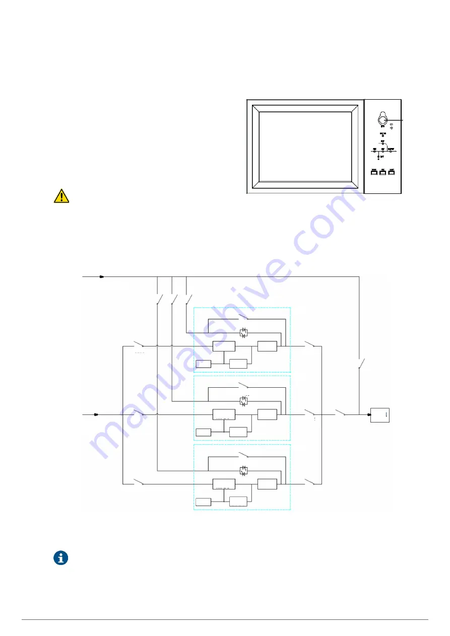
The UPS system allows up to three cabinets to be connected
in parallel. Fig. 55 shows the connections in the case of a
maximum of three UPSs in parallel.
Bypass input
BS2
BS1
BS3
Manual bypass
Manual bypass
Manual bypass
Static bypass
Static bypass
Static bypass
UPS1
UPS2
UPS3
MBS
Load
OS
OS1
OS2
OS3
AC/DC
rectifier
AC/DC
rectifier
AC/DC
rectifier
DC/AC
inverter
DC/AC
inverter
DC/AC
inverter
DC/DC
charger
DC/DC
charger
DC/DC
charger
Battery
Battery
Battery
MS1
MS2
MS3
Input
Fig. 55.
Connection diagram of three UPSs in parallel,
with independent Bypass line.
For 6-slot cabinets, configuration with independent By-
pass line is optional.
Summary of Contents for SLC ADAPT Series
Page 1: ...SLC serie ADAPT 180 300 y 500 kVA UNINTERRUPTIBLE POWER SUPPLY UPS USER S MANUAL...
Page 12: ...12 SALICRU Fig 8 Front view of 10 slot cabinet 500 kVA 300 kVA at 3x208 V with closed doors...
Page 64: ...64 SALICRU...
Page 65: ...65 SLC ADAPT UNINTERRUPTIBLE POWER SUPPLY UPS USER S MANUAL...

