43
7. CONTROL PANEL OF THE MODULES AND
THE UPS.
7.1. CONTROL PANEL OF THE MODULES.
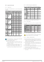
The structure of the LCDs of each module is shown in the
following Fig. 67:
1
2
3
4
1: Status LED.
2: LCD.
3: OFF button.
4. Function button.
Fig. 67.
Control panel of the power modules.
The control panel is divided into three functional areas: Status
LED, control and operation buttons and LCD.
7.1.1. Status LED.
This LED can be illuminated green or red to indicate the
different statuses and failures combining the two colours and
their permanence. These combinations can be seen in Tab. 20.
No.
LED combinations
Description
1
Green short blink 1
(ON 1 sec, OFF 2 sec)
Rectifier soft start
2
Green short blink 2
(ON 2 sec, OFF 1 sec)
Inverter soft start
3
Green medium blink
(ON 1 sec, OFF 5 sec)
Power module inverter in standby
4
Green long blink
(ON 2 sec, OFF 10 sec)
Power module asleep (shutdown)
5
Green permanently on
UPS running
6
Red and green alternating (red
1 s, green 5 s)
Charge powered with warnings
(without battery, battery in
discharge, overload, etc.)
7
Red permanently on
Power module shutdown due to
failure
8
Red medium blink
(ON 2 sec, OFF 5 sec)
Manual or software shutdown
9
Red short blink
(ON 1 sec, OFF 1 sec)
Situation none of the above
Tab. 20.
Status and failure combinations.
7.1.2. Operation and control buttons.
The operation and control buttons include FUNC buttons and
behaviour OFF buttons:
a.
The FUNC button is used to turn the pages of the display.
b.
The OFF button is mainly used to turn off the module,
such as in the following procedures:
1.
Enabled: LCD panel
→
Operate menu
→
Enable module OFF button
2.
Press the OFF button for 3 seconds, the power
module will be excluded from the system.
c.
Pressing the FUNC buttons resets the LCD.
7.1.3. LCD.
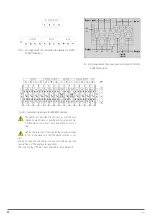
Displays module information. Its structure is shown below.
1
2
3
4
1: Selection triangle.
2: Energy flow arrow.
3: Digits.
4. Units.
Fig. 68.
Functional parts of the LCD.
The user can display the information of each module by pressing
the FUNC button to turn the pages.
•
Selecting
The input information is shown in the Digits area: voltages
and currents of the 3 phases.
•
Selecting
The output information is shown in the Digits area: voltages,
currents and load percentages of the 3 phases.
•
Selecting
The battery information is shown in the Digits area: battery
charge/discharge positive voltage and positive current and
positive bus voltage.
•
Selecting
The battery information is shown in the Digits area: battery
charge/discharge negative voltage and negative current
and negative bus voltage.
SLC ADAPT
UNINTERRUPTIBLE POWER SUPPLY (UPS)
USER'S MANUAL
Summary of Contents for SLC ADAPT Series
Page 1: ...SLC serie ADAPT 180 300 y 500 kVA UNINTERRUPTIBLE POWER SUPPLY UPS USER S MANUAL...
Page 12: ...12 SALICRU Fig 8 Front view of 10 slot cabinet 500 kVA 300 kVA at 3x208 V with closed doors...
Page 64: ...64 SALICRU...
Page 65: ...65 SLC ADAPT UNINTERRUPTIBLE POWER SUPPLY UPS USER S MANUAL...


