44
SALICRU
•
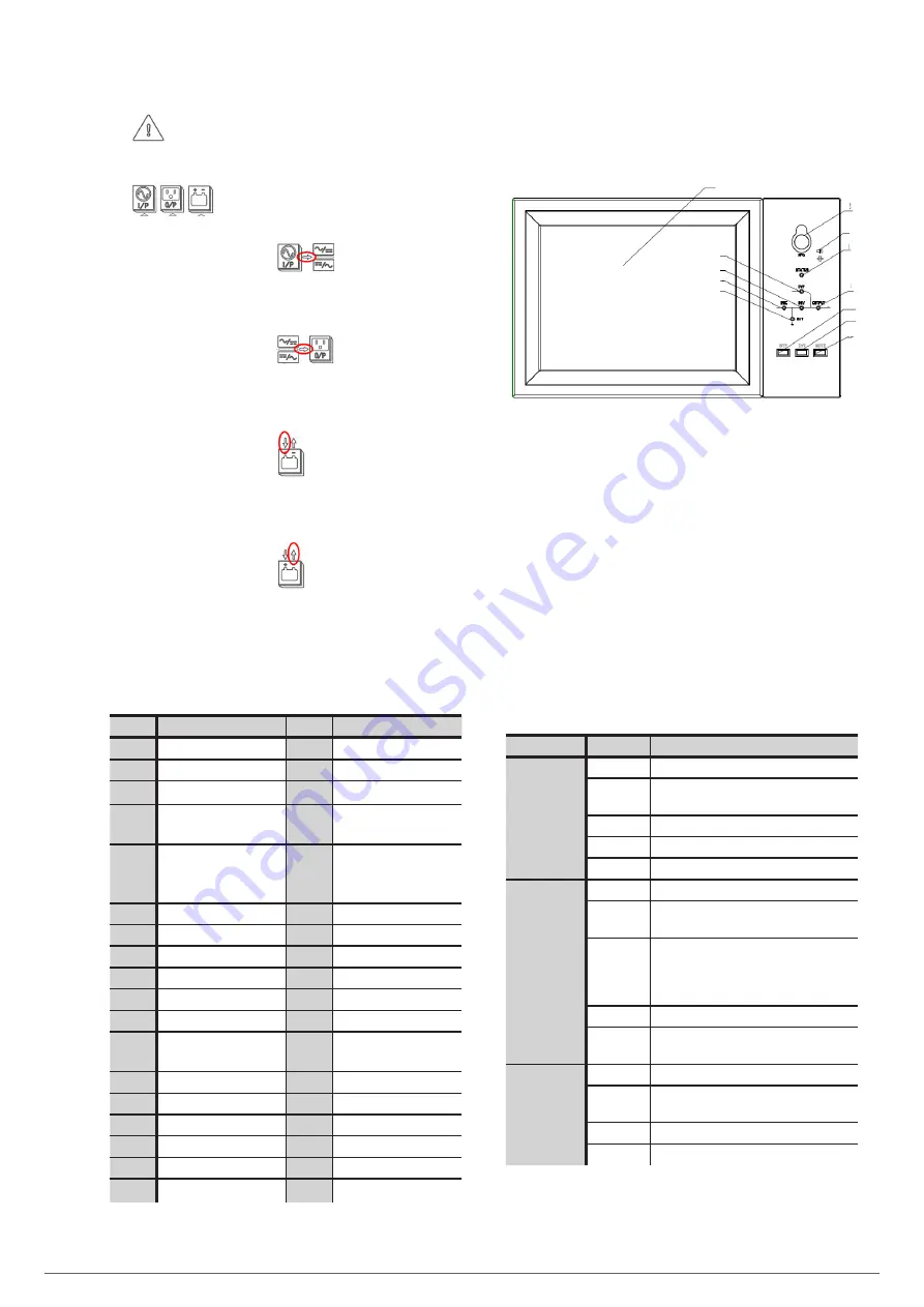
illuminated:
Failure and warning codes are displayed in the digits area.
The meaning of the codes is shown in Tab. 21.
•
blinking:
Indicates that a failure has occurred.
•
The energy flow arrow of
a.
Blinking: rectifier soft start.
b.
Illuminated: rectifier in normal operation.
c.
OFF: another situation.
•
The energy flow arrow of
a.
Blinking: Inverter starting.
b.
Illuminated: load in inverter.
c.
OFF: another situation.
•
The energy flow arrow of
a.
Blinking: low battery voltage.
b.
Illuminated: load in normal process.
c.
OFF: battery not connected.
•
The energy flow arrow of
a.
Illuminated: in discharge mode.
b.
Off: battery not connected or charging.
Unit: voltage (V), current (A), percentage (%)
When the settings on a power module have been completed,
the remainder are updated in 2 seconds.
Code
Description
Code
Description
16
Input voltage abnormal
67
Batt. polarity inverted
18
Bypass sequence failure
69
Inverter protected
20
Bypass voltage abnormal
71
Neutral disconnected
28
Bypass frequency out of
sync
74
Module turned off
manually
30
Transfer times (from
inverter to Bypass) exceed
the limit by 1 hour
81
Charger or battery failure
32
Output in short
83
Loss of N+X redundancy
34
Battery EOD
85
EOD inhibited
38
Battery test failed
93
IO CAN failure in inverter
41
Batt. maintenance failure
95
CAN data failure
47
Rectifier failure
97
Power distribution failure
49
Inverter failure
109
Inverter jumper open
51
Overtemp. in rectifier
111
Temp. difference outside
limits
53
Fan failure
113
Input current unbalanced
55
Overload
115
Overvoltage in DC bus
57
Overload time exceeded
117
Rectifier soft start failure
59
Overtemp. in inverter
119
Relay open
61
Inverter inhibited
121
Relay closed
65
Battery low
127
Manual transfer to inverter
Tab. 21.
Failure and warning codes.
7.2. UPS CONTROL PANEL.
The following figure shows the control panel:
1
2
3
4
5
7
6
9
8
10
11
12
Fig. 69.
Control panel.
1: LCD touch screen
2: EPO switch
3: Audible alarm
4: Status indicator
5: Bypass indicator
6: Rectifier indicator
7: Inverter indicator
8: Load indicator
9: Battery indicator
10: Transfer to bypass
11: Transfer to inverter
12: Mute
The LCD of the cabinet is divided into three parts: LED indicators,
control and operation buttons and LCD touch screen.
7.2.1. LED indicators.
The panel has 6 LEDs that indicate operating and failure status.
The following table shows the description of each of them.
Indicator
State
Description
Rectifier
indicator
Fixed green
Rectifier normal for all modules
Blinking
green
Rectifier normal for one or more modules,
mains normal
Fixed red
Rectifier failure
Blinking red
Mains abnormal for one or more modules
Off
Rectifier not operational
Battery
indicator
Fixed green
Battery charge
Blinking
green
Battery discharge
Fixed red
Battery abnormal (battery failure, no battery
or battery inverted) or abnormal battery
converter (failure, overcurrent, excess
temperature), EOD
Blinking red
Low battery voltage
Off
Battery and battery converter normal, battery
not charging
Bypass
indicator
Fixed green
Load supplied by bypass
Fixed red
Bypass abnormal or out of range, or static
bypass switch failure
Blinking red
Bypass voltage abnormal
Off
Bypass normal
Summary of Contents for SLC ADAPT Series
Page 1: ...SLC serie ADAPT 180 300 y 500 kVA UNINTERRUPTIBLE POWER SUPPLY UPS USER S MANUAL...
Page 12: ...12 SALICRU Fig 8 Front view of 10 slot cabinet 500 kVA 300 kVA at 3x208 V with closed doors...
Page 64: ...64 SALICRU...
Page 65: ...65 SLC ADAPT UNINTERRUPTIBLE POWER SUPPLY UPS USER S MANUAL...


