46
SALICRU
The structure of the main menu is shown in the following
diagram:
Bypass
Cabinet
Input
Output
Loads
Batteries
Input
Output
Load
Information
Code-S
Module
Settings
Log
Operation
Charts
Date and time
Language
Communications
User
Battery
Service
Rated
Configuration
Mute
Restart log
Activate
Bypass mode
Activate
inverter mode
Battery test
Battery
maintenance
Quick battery
charging
Battery float
Output voltage
Output current
Bypass
voltage
Start
Fig. 71.
Menu tree structure.
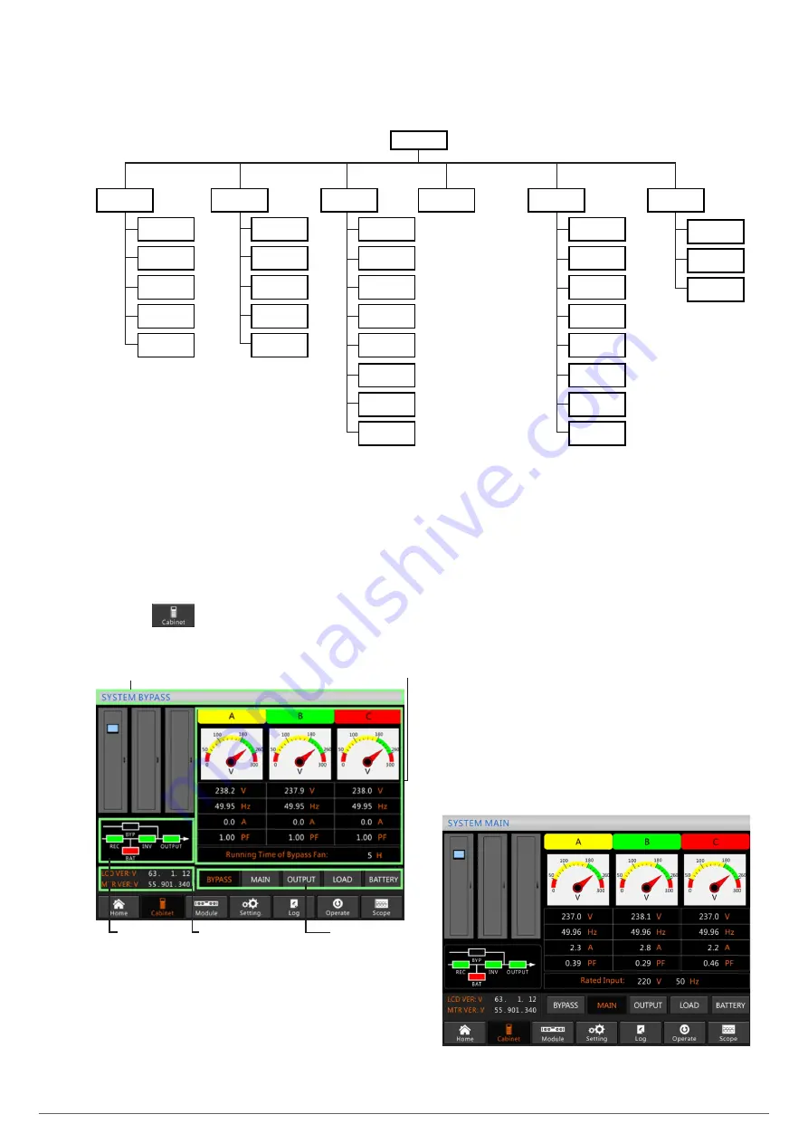
7.3. MAIN MENU.
The main menu includes Cabinet, Module, Settings, Log, Op-
eration and Graphics, as described below:
7.3.1. Cabinet.
Press icon
in the lower left corner of the screen to
access the Cabinet screen.
Name
Information display
Operating status
Submenu
Version
information
Fig. 72.
Cabinet screen.
This menu includes the following parts: title, operating status,
version information, submenu and information display.
•
Title
Displays information about the selected submenu.
•
Operating status
The boxes shown in the block diagram represent the
different elements and show the current operating status
of the UPS.
a) Green indicates that the block is working normally
b) White indicates the absence of the block
c) Red indicates the absence or failure of the block
•
Version information
Displays version information for the LCD of the cabinet and
monitor.
•
Submenu
Includes the submenu with options Input, Bypass, Output,
Loads and Batteries.
•
Information display
Displays information about the submenus. The interface
of each submenu is shown in Fig. 72 (Bypass option) and
Fig. 73 (other options).
a.
Interface of Input option
Summary of Contents for SLC ADAPT Series
Page 1: ...SLC serie ADAPT 180 300 y 500 kVA UNINTERRUPTIBLE POWER SUPPLY UPS USER S MANUAL...
Page 12: ...12 SALICRU Fig 8 Front view of 10 slot cabinet 500 kVA 300 kVA at 3x208 V with closed doors...
Page 64: ...64 SALICRU...
Page 65: ...65 SLC ADAPT UNINTERRUPTIBLE POWER SUPPLY UPS USER S MANUAL...


