11
4.3. GENERAL DESCRIPTION.
The SLC ADAPT X series is classified as an on-line double
conversion Uninterruptible Power Supply with DSP control and
three-level IGBT inverter technology, modular topology and
high flexibility.
Reliability:
The DSP control associated with three-level PWM
technology extends the system efficiency and, together with
module redundancy, significantly extends the mean time be-
tween failures, MTBF.
Availability:
Its “hot-swap” modules can be added or replaced
during operation, thereby improving the mean time to repair
-MTTR- and reducing maintenance costs. Moreover, both the
control display and the bypass module can be replaced without
affecting the operation of the device. In addition, the system’s
remote management, which can be integrated into any plat-
form, also facilitates operation. The extensive back-up options
available, along with smart battery charging, ensure continuous
operation of the protected critical loads.
Flexibility:
It allows configurable solutions from 10 to 450
kVA, combining power modules of 10 and 15 kVA with the dif-
ferent available subracks of 2, 4 and 6 slots and the parallel of
up to 5 subracks of the last one, only this last format allows its
paralleling.
This enables the gradual upgrading and scaling of the power of
the equipment according to the need for protection "pay as you
grow", improving the total cost of ownership [TCO] and a high
level of flexibility.
At the operational level it is considered as a single UPS, a sub-
rack formed by 'N' modules or different subracks connected
together in parallel.
Any expansion or structural modification in the number of mod-
ules is possible even during normal operation, without implying
that the hot-swappable system should stop, all with the help
of a screwdriver used to remove or tighten the fixing screws of
the module/s.
Input-output configuration:
Originally the system can be
shipped from the factory with different types of input and
output or can be modified at site by our
T.S.S.
and/or distribu-
tors.
It is not allowed or authorized to change the configuration by
the end-user, since this involves the modification of copper
rods between the power terminals by the addition or removal
of them, in order to get the required configuration, moreover
changes are necessary in the parameters of the access menus
by "Password" through the control panel.
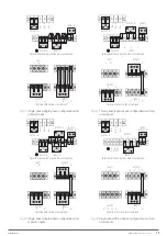
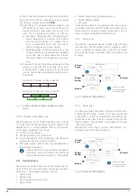
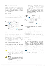
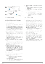
The possible input/output configurations are:
•
Three-phase/three-phase.
•
Single-phase/single-phase.
•
Single phase/three phase.
•
Three-phase/single-phase.
In 10 kVA modules, the output power factor 1 is kept for any of
the configurations.
Autonomy:
The capacity of the batteries determines the back
up time of the system that will supply its usual source of energy
during the mains failures. The battery set is always common to
any module assembled in the same subrack.
Batteries, owned by the customer or supplied together with
the UPS, and depending on different factors in addition to the
power and/or autonomy requested, can be installed on a rack in
one or more cabinets, or in the cabinet of the equipment itself
when the subrack is assembled in a 19” rack cabinet.
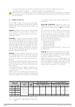
Typology of the
power supply
Input and output
voltage
(V)
Power per
module
(kVA)
Subrack power range (kVA)
System power range (kVA)
Number of modules per subrack
Number of subracks of 6 slots in parallel
Input
Output
1.. 2
1.. 4
1.. 6
2
3
4
5
III
III
3x380.. 3x415
(Three N)
220.. 240
(Phase and neutral
-N-)
10
10.. 20
10.. 40
10.. 60
10.. 120
10.. 180
10.. 240
10.. 300
I
I
I
III
III
I
III
III
15
15.. 30
15.. 45
(1)
15.. 90
15.. 180
15.. 270
15.. 360
15.. 450
(1)
Maximum 3 modules of 15 kVA due to the limitation of the static bypass block.
Tabla 1.
SLC ADAPT X configurations and their power
range.
connection of the equipment. This applies only when the two power lines come from two different grids, such as:
- Two different electricity companies.
- An electricity company and a power generator, etc.
(
1
)
In the case of UPSs with different input and output frequencies or frequency converters, the static bypass is disabled and
the manual bypass switch of the equipment must not be operated, because the input frequency and the frequency required by
the load are different.
EMi3
SERVOMOTOR VOLTAGE STABILISER
USER'S MANUAL

