12
SALICRU
4.3.1. Introduction.
The SLC ADAPT X series UPS basically consists of:
•
Subrack with 2, 4 or 6 slots to install the power modules.
•
Power modules, consisting of the following blocks:
PCF-Rectifier-AC/DC-.
Battery charger.
Inverter -DC/AC-.
Digital control and UPS management.
•
Centralized bypass module: control of UPS and parallel pa-
rameters.
•
Maintenance bypass
•
Control panel with touch screen (see section 7 for more in-
formation).
•
Batteries (Quantity, type and location depending on the
back-up time).
4.3.2. Architecture.
4.3.2.1. Structural diagram.
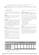
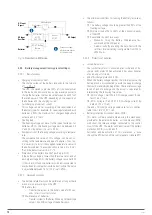
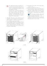
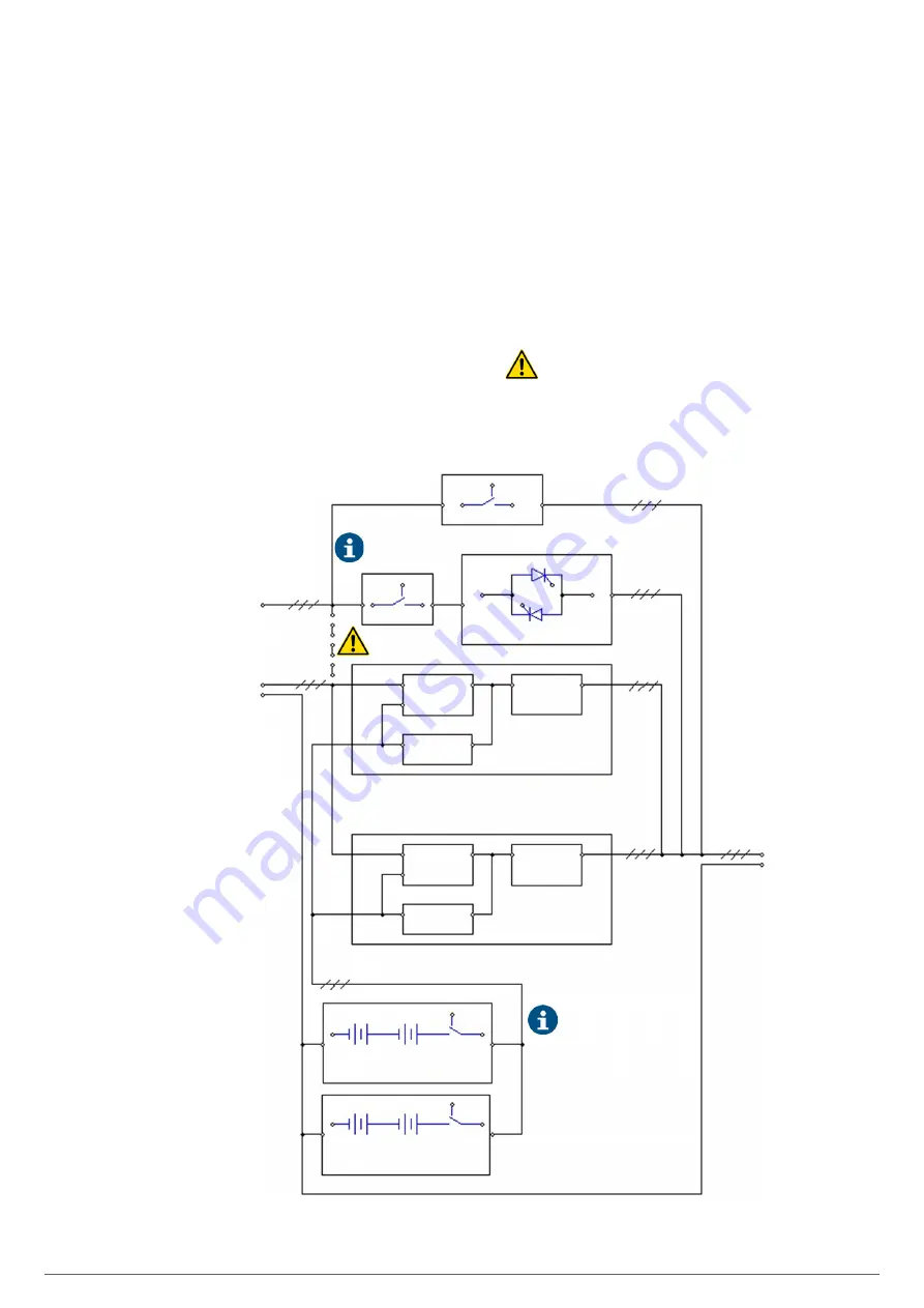
Fig. 4 shows a single-line diagram of the equipment with three-
phase input and output, as an example.
All subrack units are structured according to the same criteria,
separate power supply for the PFC-rectifier and static bypass.
However, unless otherwise requested, separate grids, origi-
nally from the factory will connect the terminals of the phases
of both blocks by means of the copper rods in order to have a
single common input.
When separate power supplies are required, it is man-
datory to remove the copper rods between phases of
both blocks before connecting the power cables,
leaving the one for the neutral terminals.
STATIC BYPASS MODULE
DC / AC
INVERTER
MANUAL BYPASS
REC / PFC
BAT / DC
DC / DC
INVERTER
BYPASS
STATIC BYPASS LINE INPUT
-R, S, T-
N
POWER MODULE # 1
DC / AC
INVERTER
REC / PFC
BAT / DC
DC / DC
INVERTER
POWER MODULE #N
•
•
•
OUTPUT U, V, W
N
BATTERY MODULE
BCB
BATTERY MODULE
BCB
Connection copper rod
between phases for
common grid.
Q1
Q2
UPS INPUT
-R, S, T-
Not installed in 6-slot
sub-rack.
The batteries are represented in
the structural scheme as they are
an essential part of any UPS,
although they will never be
included in the sub-rack itself. The
batteries can be supplied in the
same rack cabinet in which the
ADAPT subrack is assembled, in a
separate cabinet, on a rack or
when the customer does not have
them available, not supply them
at all.
Fig. 4.
Structural single-line diagram as an example.

