14
SALICRU
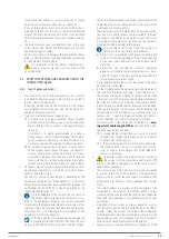
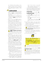
PE
Output U
Output V
Output W
Bypass R
Input R
Bypass S
Input S
Bypass T
Input T
Bypass N
Input N
Bat. +
Bat. N
Bat. –
OUTPUT N
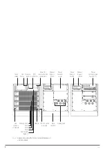
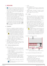
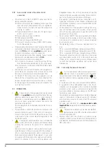
Terminal block in 2-slot and 4-slot subrack.
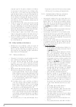
BATT
+ N –
BYPASS
R S T N
INPUT
R S T N
OUTPUT
U V W N
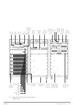
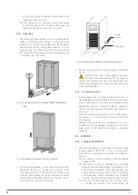
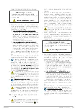
Terminal block in 6-slot subrack.
Fig. 6.
Terminal block for three-phase/three-phase con-
figuration and separate inputs (PFC-rectifier and
static bypass).
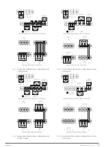
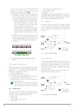
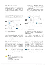
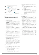
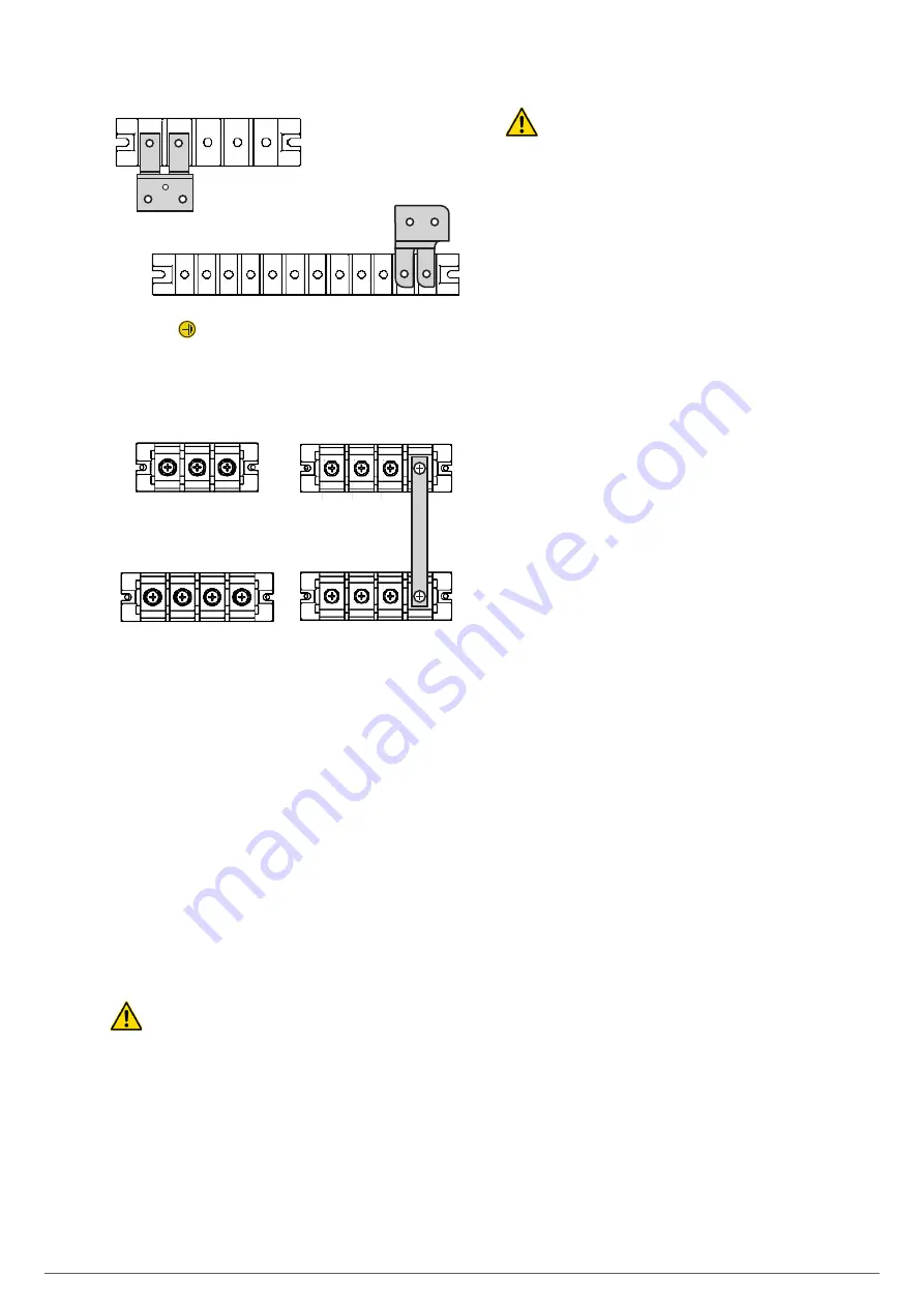
The illustrations of Fig. 5 and 6 show the arrangement of the
connection terminals on three-phase/three-phase input/output
equipment. For other configurations see Fig. 7 to 10.
4.3.2.1.3. Manual bypass switch for maintenance.
The equipment has a manual bypass switch useful for periods
of preventive maintenance or repairing. This switch transfers
the load power directly onto the AC input mains, allowing the
intervention on the UPS without disturbing the feeding of the
loads.
When the UPS is operating in bypass mode (over static
bypass) or manual bypass mode (maintenance or re-
pairing period), connected equipment is not protected
against power outages or blackouts, overvoltages,
voltage and/or frequency fluctuations, as they are di-
rectly fed from the commercial AC grid.
Before operating this switch it is necessary to transfer the load
power over the static bypass through the respective command
from the touch screen. The switching of the power mode on
the static bypass and from that to the manual bypass is done
without interruption in the supply of the load.
When a subrack is assembled inside a cabinet, the
input, output and static bypass protections must be in-
stalled, as well as a manual bypass switch, on the front
of the enclosure itself to facilitate all operations.
Respect the selectivity indicated in the documentation
referred to in the "Recommended Installation” docu-
ment downloaded from the website or supplied in the
CD-ROM or Pen Drive.
Section 6.4 describes all operations related to the manual
maintenance bypass.
4.3.2.2. Parallel system.
4.3.2.2.1. Parallel system considerations.
•
All UPS modules have hardware and software that is suit-
able and compatible with the requirements of parallel sys-
tems.
•
Although all modules installed in a subrack are internally
connected in parallel, the parallel connection between
subracks is only possible in those of 6 slots, with their
series available on the communication board for this func-
tion, having a maximum of up to 5 subracks -30 modules-.
The resulting power range, according to the input-output
typology, and the individual power of each module, is re-
flected in Tab. 1.
•
The hardware adjustments referring to the change of input
and output configuration are reserved exclusively to the
manufacturing process itself or subsequently at site pro-
cess performed by the
T.S.S.
•
The subracks are supplied with a single power terminal and
control bus connectors.
Depending on the power of the system the input and output
connections are made by cables or against a busbar when
the currents or the installation condition it.
Using the DB15 signal connectors, the control bus is con-
nected in the form of a closed ring, linking the different
subracks that configure the system in parallel.
Smart parallel logic provides maximum flexibility to the
user. For example, shutting down or starting up a parallel
system can be done in any sequence, through any sub-
rack. In a parallel system as in a single subrack, transfers
between Normal and Bypass modes and vice versa are
synchronized. For example, once an overload of a parallel
system is detected and processed, it is automatically trans-
ferred to Bypass. If the overload disappears, the parallel
system automatically recovers the normal operation, trans-
ferring the load from Static Bypass to the Inverter.
•
Usually the sizing of a parallel system is based on the
power required by the loads, plus the modules in redun-
dancy that are estimated with the expression N+n; where
“N” is the number of modules in parallel in order to obtain
the required nominal power and “n” is the number of redun-
dant equipments.
Beyond this planned over-sizing, all the modules are oper-
ated by load sharing, delivering the same power to get the
total amount required, which implies a lower efficiency
than desired.

