15
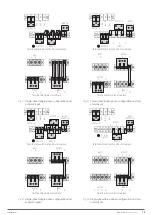
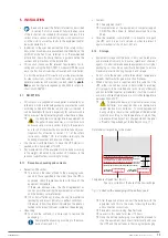
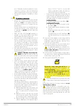
Bat. +
Bat. N
Bat. –
OUTPUT N
INPUT N
INPUT R
OUTPUT U
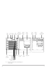
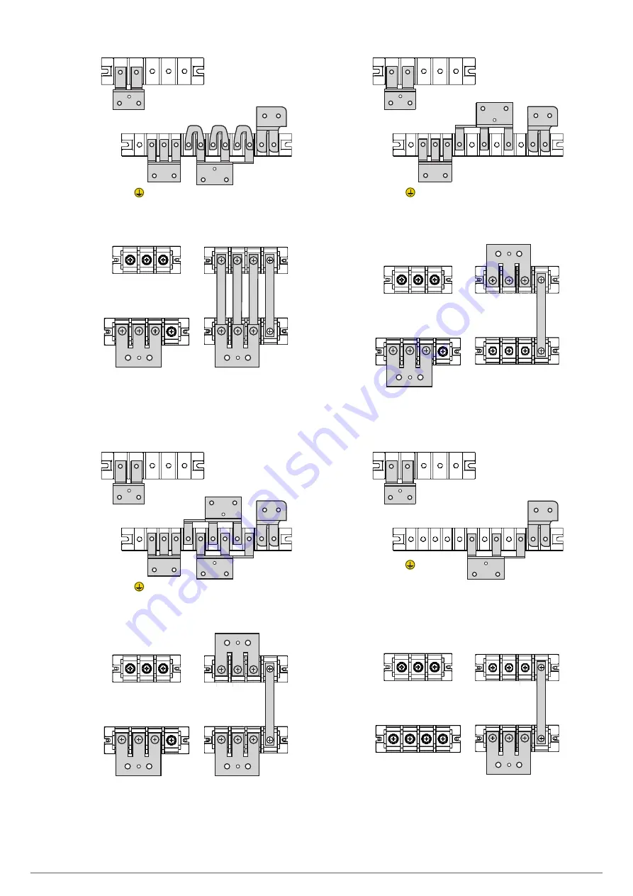
Terminal block in 2-slot and 4-slot subrack.
BATT
+ N –
INPUT
R N
OUTPUT
U N
Terminal block in 6-slot subrack.
Fig. 7.
Single-phase/single-phase configuration and
common input.
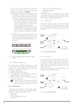
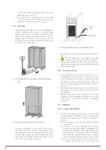
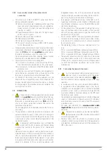
Bat. +
Bat. N
Bat. –
OUTPUT N
BYPASS R
INPUT /
BYPASS N
INPUT R
OUTPUT U
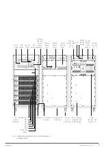
Terminal block in 2-slot and 4-slot subrack.
BATT
+ N –
BYPASS
R N
INPUT
R N
OUTPUT
U N
Terminal block in 6-slot subrack.
Fig. 8.
Single-phase/single-phase configuration and
separate inputs.
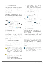
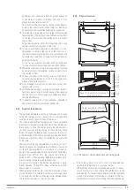
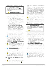
Bat. +
Bat. N
Bat. –
OUTPUT N
BYPASS R
INPUT /
BYPASS N
R
S
T
INPUT
OUTPUT U
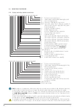
Terminal block in 2-slot and 4-slot subrack.
BATT
+ N –
BYPASS
R N
INPUT
R S T N
OUTPUT
U N
Terminal block in 6-slot subrack.
Fig. 9.
Three-phase/single-phase configuration and sep-
arate inputs.
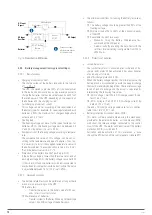
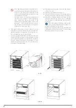
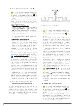
Bat. +
Bat. N
Bat. –
OUTPUT N
BYPASS
R
S
T
INPUT /
BYPASS N
INPUT R
U V W
OUTPUT
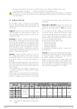
Terminal block in 2-slot and 4-slot subrack.
INPUT
R N
OUTPUT
U V W N
BYPASS
R S T N
BATT
+ N –
Terminal block in 6-slot subrack.
Fig. 10.
Single-phase/three-phase configuration and sep-
arate inputs.
EMi3
SERVOMOTOR VOLTAGE STABILISER
USER'S MANUAL

