16
SALICRU
In order to solve this problem and increase the efficiency of
the system, one of the two sleep modes can be activated
from factory or subsequently by the
T.S.S.
:
Smart Sleep. This advanced technology applied to the
UPS ADAPT series, allows you to look for the point of
maximum efficiency, even when working with small
loads. This is achieved by activating one of the two
possible modes, although each has a different purpose:
–
Normal Sleep mode. The inverter of the modules
with the option activated is in standby, with its
output disconnected from the load. The time for
them to finish operating is a few seconds.
–
Deep Sleep mode. All the power converters of the
modules with the option activated are completely
off and the output is disconnected from the load.
The time for them to finish operating is a few min-
utes.
In addition to this and to get the same ageing of all the
modules, a cycling function is available. This consists
of alternating the stopped modules with those that are
running. The minimum programmable cycling period is
three months.
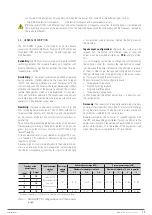
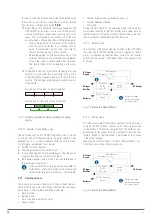
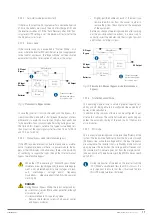
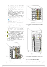
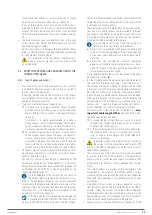
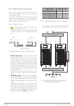
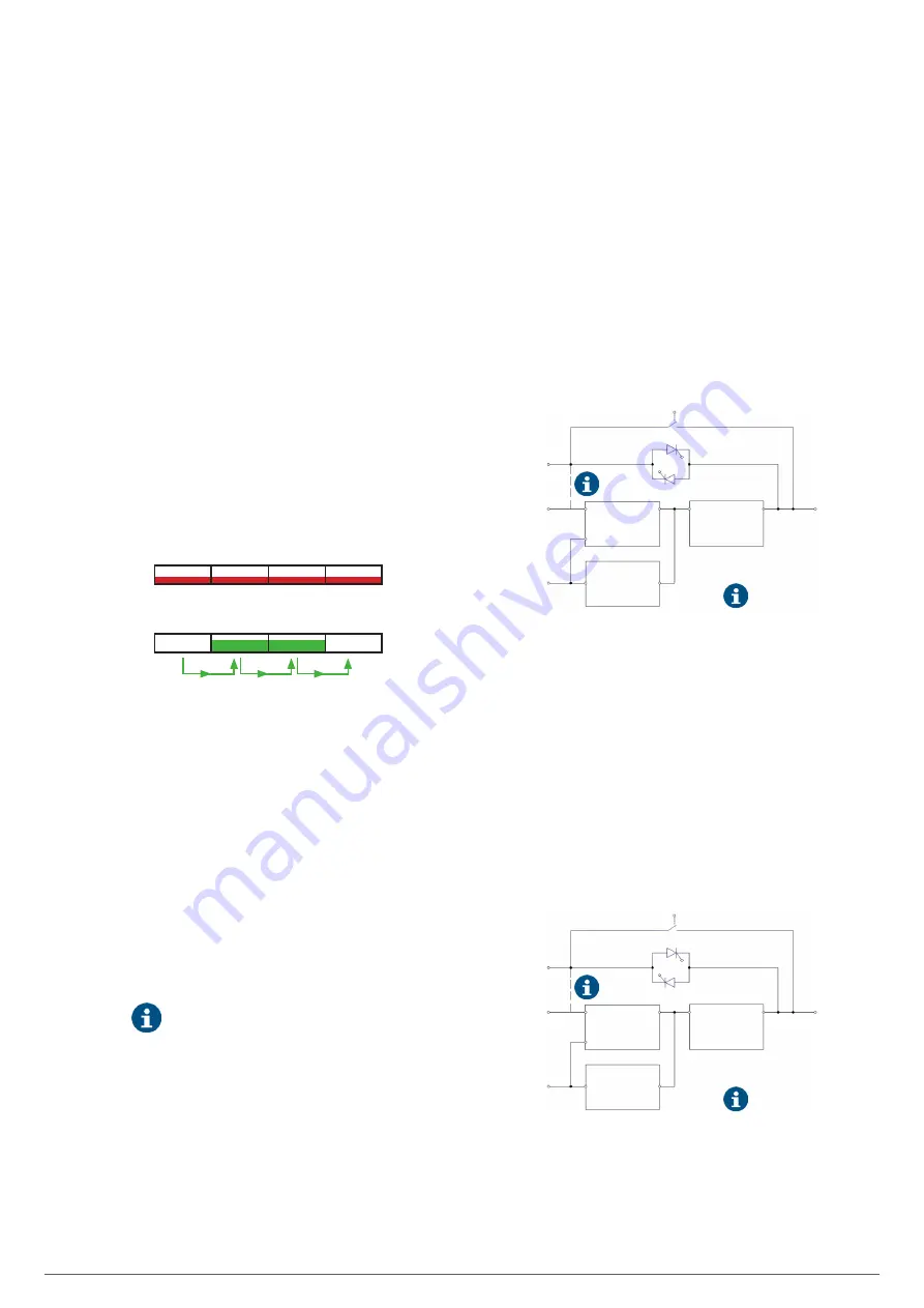
Distribution of the load in normal operation.
Distribution of loads and cycling of the UPS.
Fig. 11.
Graphic example of normal operation or cycling
modes.
4.3.2.2.2. Features of the parallel system
The performance of an SLC ADAPT X parallel system is similar
to a large UPS with the advantage of greater reliability and
adaptability. For a system to operate correctly with the load,
the following requirements must be met:
1.
All UPSs must be identical.
2.
Must be powered by the same AC line.
3.
In case of equipment with separate bypass line, the power
supply grid will be the same for all of them.
4.
Both power supplies, points 2 and 3, must be referenced to
the same neutral potential.
Isolation transformers are optionally available for
installations where both sources do not share the
same neutral reference or where it is not available.
4.3.3. Operating modes.
The modular system described is part of the on-line double con-
version UPS family, with static bypass line and manual mainte-
nance bypass. The available operating modes are:
•
Normal mode.
•
Battery mode.
•
Auto-start mode (automatic start).
•
Bypass Mode.
•
Manual bypass mode (maintenance bypass).
•
Parallel-Redundant Mode.
•
ECO mode.
During the description of the operating modes the operation
is described referring to the PFC-rectifier and inverter parts as
functional parts of a module, although there will be as many of
them as modules connected in parallel there are.
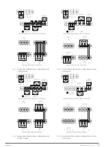
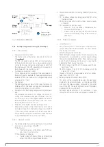
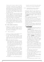
4.3.3.1. Normal mode.
The inverter of the power module installed in the UPS feeds
the critical load. The PFC-rectifier, which is supplied by the AC
mains, simultaneously supplies direct current to the inverter
and the battery charger, which keeps them in an optimal state
of charge.
PFC rectifier
AC/DC
BAT / DC
DC / DC Battery
Charger
Inverter
DC / AC
Static bypass
Manual bypass
Batteries
AC Input
Bypass
AC Input
Rectifier
AC Output
Connection copper
rods between phases
for common input.
Fig. 12.
Flowchart in Normal Mode.
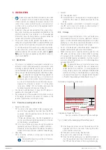
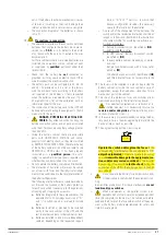
4.3.3.2. Battery mode.
This mode is activated in the event of any fault in the AC mains,
in which the PFC-rectifier switches its AC mains input power
to the battery. The inverter, powered from the batteries, sup-
plies power to the critical load. This automatic transition from
"Normal Mode" to "Battery Mode" is performed with no break
in the output voltage.
When the AC mains voltage is restored, "Normal Mode" is au-
tomatically reset without any intervention.
PFC rectifier
AC/DC
BAT / DC
DC / DC Battery
Charger
Inverter
DC / AC
Static bypass
Manual bypass
Batteries
AC Input
Bypass
AC Input
Rectifier
AC Output
Connection copper
rods between phases
for common inputs.
Fig. 13.
Flowchart in Battery Mode.


