17
4.3.3.3. Auto-start mode (automatic start).
If there is a failure of the AC input power for an extended period
of time, the battery may reach the end of discharge -EOD- and
the inverter switches off. If the "Auto Recovery after EOD" (fac-
tory preset) UPS setting is set, the device will restart after the
the AC power is restored.
4.3.3.4. Bypass mode.
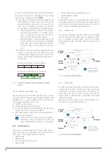
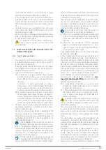
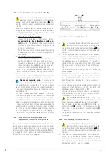
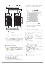
If the inverter capacity is exceeded in "Normal Mode", or in
cases where the inverter-PFC-rectifier set can not supply power
to the load for any reason, the "Bypass Mode" will be activated
automatically without interruption of service at the output.
PFC rectifier
AC/DC
BAT / DC
DC / DC Battery
Charger
Inverter
DC / AC
Static bypass
Manual bypass
Batteries
AC Input
Bypass
AC Input
Rectifier
AC Output
Connection copper
rods between phases
for common input.
Fig. 14.
Flowchart in Bypass mode.
In case the inverter is not synchronized with the bypass, this
transition will be made with a short break at the output of a few
milliseconds to avoid the occurrence of high current peaks due
to the parallel of non-synchronized alternating voltage sources.
The time of this break is variable, the typical value being less
than ¾ parts of the input signal cycle (less than 15 ms for 50 Hz
and 12.5 ms for 60 Hz).
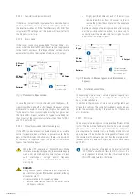
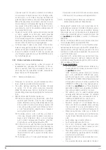
4.3.3.5. Manual bypass mode (maintenance bypass).
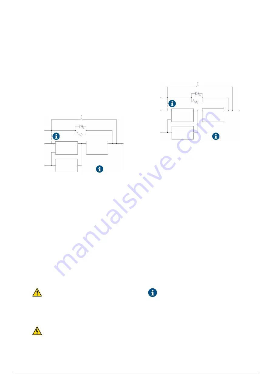
If the UPS requires intervention due to breakdown or mainte-
nance (for example, because there is a power module, the by-
pass or the LCD display with anomalies), there is the possibility
of continuing to supply the loads through the internal manual
bypass (maintenance bypass).
When the UPS is operating in "Manual Bypass Mode”
(maintenance or repairing period), the connected equip-
ment is not protected against power outages or black-
outs, overvoltages, voltage and/or frequency
fluctuations, ... when are directly fed from the commer-
cial AC grid.
DANGER:
During Manual Bypass Mode, the input, output and by-
pass terminals [version B] are under potential, although
all modules are off.
It is recommended in this operating mode:
–
Remove the fastening screws of all power, control
and bypass modules.
–
Slightly pull the handles on each of them until you
remove them 4-5 cm from the socket, in order to
remove them from the connector on the backplane
of the equipment.
Before any change of operating mode and after carrying
out the possible corrective actions, it is necessary to
correctly insert the modules into their original position
and fix them with their screws.
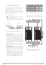
PFC rectifier
AC/DC
BAT / DC
DC / DC Battery
Charger
Inverter
DC / AC
Static bypass
Manual bypass
Batteries
AC Input
Bypass
AC Input
Rectifier
AC Output
Connection copper
rods between phases
for common input.
Fig. 15.
Flowchart in Manual bypass mode (maintenance
bypass).
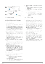
4.3.3.6. Parallel-Redundant Mode.
This operating mode allows to obtain a greater capacity, reli-
ability or both, being able to be configured like upgrading of
power or like redundancy.
In addition in the subracks of 6 slots can be configured in par-
allel up to 5 subracks. The controller included in each one guar-
antees the automatic sharing of the load in all of them and in
all its modules.
4.3.3.7. ECO mode.
This is a special operating mode to improve the efficiency of the
system. The load will be fed directly from the AC mains through
the bypass line, while the voltage and/or the input frequency
are acceptable. The inverter that is in Standby mode will start
up and power the load when the voltage and/or frequency of
the commercial AC network goes out from the margins estab-
lished as nominal. The performance in the ECO Mode can reach
up to 98%.
During the transfer of the load on the inverter from the
"ECO Mode" a small break (less than 10 ms) occurs. It is
very important to ensure that the critical load fed into
this UPS mode, tolerates that break.
EMi3
SERVOMOTOR VOLTAGE STABILISER
USER'S MANUAL


