18
SALICRU
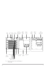
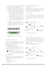
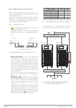
PFC rectifier
AC/DC
BAT / DC
DC / DC Battery
Charger
Inverter
DC / AC
Static bypass
Manual bypass
Batteries
AC Input
Bypass
AC Input
Rectifier
AC Output
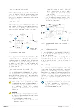
Connection copper
rods between phases
for common input.
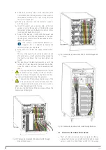
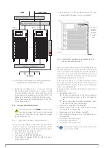
Fig. 16.
Flowchart in ECO mode.
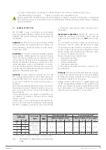
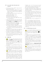
4.3.4. Battery management (factory preset settings).
4.3.4.1. Basic functions.
•
Charging at constant current.
The charge current of the battery responds to the formula
of I
ch
= 0.2 x C
The UPS is designed to provide 100% of its nominal power
to the load and additionally has a unique reserve power to
charge the batteries that can be set between 0 and 20% of
the rated power of the UPS, depending on the capacity of
the batteries and the charging current.
•
Fast charging at constant current.
This voltage can be set according to the requirements of
the battery type. For example, for valve-regulated lead-acid
batteries -VRLA-, the maximum fast charge voltage should
not exceed 2.4 V / cell.
•
Floating load.
The floating voltage can be set to the type of batteries. For
batteries -VRLA-, the floating voltage must be between 2.2
V and 2.3 V. By default it is set to 2.25 V.
•
Compensation of the floating voltage according to tempera-
ture.
The compensation value of this voltage can be set ac-
cording to the temperature and type of batteries. To do this,
it is necessary to install the supplied temperature sensor in
the battery cabinet. The compensation range is 0 to 5 mV /
ºC and the default value is 3 mV / ºC.
•
Protection of the battery by end of discharge -EOD-.
If the battery voltage is lower than the value set as end of
discharge voltage -EOD-, the battery voltage converter BAT
/ DC will turn off and the batteries will be disconnected to
avoid a deep discharge that could be destructive. The value
is adjustable between 1.6 to 1.75 V / cell -VRLA-.
4.3.4.2. Advanced functions.
•
Two battery-related tests can be performed as long as there
are no alarms or warnings on the UPS.
Battery test:
–
Transfer the system to the battery mode for 20 sec-
onds to test its correct status.
Maintenance of batteries:
–
Transfer system to "Batteries Mode" up to the voltage
value -1.05 x EOD voltage of the battery pack.
•
The minimum conditions for running the battery test are as
follows:
The battery voltage should be greater than 90% of the
floating voltage.
Minimum load of 25 to 100% of the nominal capacity
of the UPS.
Executable in one of two ways:
–
Manually. Using the Battery Maintenance Test
command on the LCD panel
–
Automatically. By enabling the Auto-Test with the
self-test interval setting (configurable from 720 to
3000 hours).
4.3.4.3. Protection of batteries.
•
Low battery alarm.
The low battery alarm is activated prior to the end of dis-
charge -EOD- alarm. When activated it has about minutes
of autonomy at full load.
•
End of discharge protection -EOD-.
When the battery voltage reaches this minimum value, the
battery block is disconnected to avoid the deep discharge
that could irreversibly damage them. There are two voltage
levels of end of discharge and the actual is calculated by
interpolating the following two values:
-EDO- Voltage / Cell @ 0.6 C Discharge current. By de-
fault 1.65 V / cell.
-EDO- Voltage / Cell @ 0.15 C Discharge current. By
default 1.75 V / Cell)
The end of discharge voltage values are factory configu-
rable from 1.6 to 1.75 V / cell.
•
Battery protection disconnect alarm -MCB-.
This alarm will be available when using the mechanism
provided for the external batteries, a circuit breaker -MCB-
with shunt trip release voltage connected to the control
circuit of the UPS. The alarm will be activated if the battery
protection -MCB- is switched off.
Activation and deactivation of this protection is done
through the EPO button on the control panel or remote EPO.

