27
nals of the battery to external mechanical stresses
of tension or twisting, as they can damage their
internal connection and in very serious cases ignite.
–
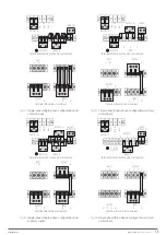
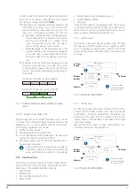
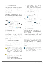
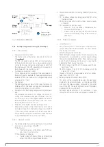
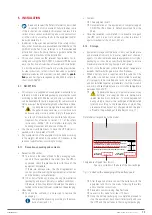
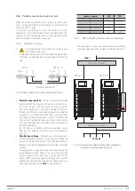
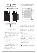
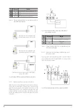
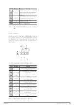
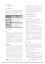
The connection diagram of the batteries is shown
in Fig. 27.
Precautions in connection.
–
The operations referred to the connection between
batteries that configure the battery block are re-
served to our
T.S.S.
or in its defect to the distrib-
utor, reason why they are not treated in the user
documentation.
For those cabinets where user-owned batteries are
installed, the operations will be carried out and/
or supervised by
qualified
personnel under their
responsibility.
–
Check that the battery
is not
connected or
grounded, as it may cause an electric shock. Other-
wise disconnect the electrical connection.
–
The battery pack can be configured to 32, 36, 40
and 44 12V elements and it is set at the factory
with the number of cells according to the battery
set supplied or the number of items requested
when the batteries are owned by the user. If not,
32 elements [16 + 16] will be calibrated, with an
information label for the user.
–
The connection of the battery pack to the UPS will
be done before connecting the equipment to the AC
mains or with the load.
–
DANGER, POTENTIAL OF LETHAL BAT-
TERIES.
Pay attention when handling the
battery connection cables and all parts associated
with them. Terminal block battery voltage greater
than 400 V DC.
–
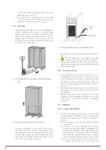
Inside the battery cabinet there are accessible
parts with HAZARDOUS VOLTAGE and conse-
quently risk of electric shock, so they are classified
as RESTRICTED ACCESS AREAS. Therefore the key
of the battery cabinet will not be available to the
OPERATOR or USER, unless it has been properly
instructed or is a
qualified person
. This cata-
loging is applicable to battery rooms, regardless of
whether they can be installed or not on a rack.
–
Do not operate the battery switches until indicated.
–
The protection of batteries will always be carried
out at least with fuses and their physical arrange-
ment will be conditioned to the tangible location of
the batteries themselves.
The following are the different assemblies made by
our firm and the location of the battery protection
for each case, which is necessary for the operations
of running and stopping the assembly:
a.
Batteries integrated in the same cabinet as the
equipment or in its homologous version of “0/”
and “/” in which space is reserved to include
them.
b.
Batteries installed or planned to be installed
partly in the own cabinet of the UPS and the
rest in another cabinet or other cabinets or rack.
c.
Batteries installed in one or more independent
cabinets, depending on the requested support
time or "0/" and "/" versions, in which their
backup configuration reserves the necessary
space for the location of the batteries.
–
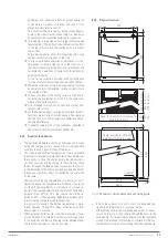
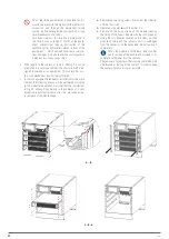
As a result of the arrangement of the batteries, the
switch and/or the respective protection shall be ar-
ranged as follows and identified in the illustrations
in document EL096*00 according to each case as:
Assemblies type ‘
a.
'.
1.
Battery disconnect switch, identified as
(Q3)
.
Assemblies type ‘
b.
‘ and ‘
c.
‘.
1.
In UPS cabinet. Battery disconnect switch,
identified as
(Q3)
.
2.
In every battery cabinet. Depending on protec-
tion size:
Battery fuse-holder switch with 3 fuses, refer-
enced as
(F3)
.
Or battery disconnect switch, identified as
(Q8)
and three internal fuses not accessible to the
user.
The fuses will be supplied in a plastic bag inside the
battery cabinet or inside the rack cabinet in case of
adaptations, except the fixed ones, since they form a
mechanical part of the cabinet.
The size of the protection fuses and switches are di-
mensioned according to the initial start-up power.
Any modification (extension or reduction of in-
stalled modules) will necessarily involve the
revision and/or adaptation
of the installation (cross
sections, protection sizes, ...).
In the same way, it is recommended to enlarge the bat-
tery pack in case of power upgrading to maintain the
back-up time as much as possible.
The original factory battery circuit is open.
– +
Operate the switch and/or place the fuses
in the
corresponding fuse holder switch and operate to "ON”
only when indicated
, not before. Failure to do so may
cause
irreversible damage to the equipment or se-
rious and/or very serious accident
to the installer
by exposing it to a possible
electric shock
during the
connection of the UPS to the battery pack or to the bat-
tery cabinet.
•
Do not operate the battery fuse holder switch and/
or the disconnect switch when the equipment is run-
ning.
In assemblies made by our firm, these mechanisms
are not
load break type switches
.
•
When a equipment or the parallel system is ex-
pected to be out of service for an extended period of
time, the complete shutdown must be carried out before-
hand and the 3 fuses of the fuse holder switch of the equip-
ment or the battery module are removed for safety and
stored in a safe place.
EMi3
SERVOMOTOR VOLTAGE STABILISER
USER'S MANUAL


