30
SALICRU
5.5.3. Connection of the output, terminals
(X6 to X9)
.
•
As it is an equipment with protection against class I
electrical shock, it is essential to install the protec-
tive earth conductor to the terminal identified as
. Con-
nect this conductor before supplying voltage to the input
terminals.
•
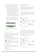
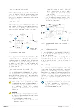
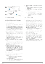
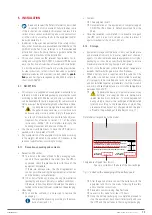
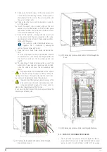
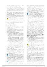
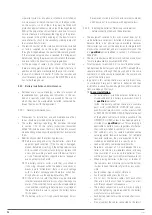
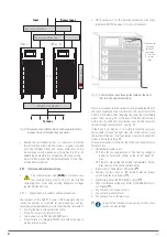
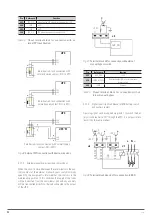
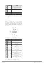
Connect the output cables to the respective terminals ac-
cording to the configuration of the available equipment,
considering the illustrations in Fig. 5 to 10 in terms of the
connection points of the cables.
Three-phase output connection:
Connect the loads to the U-V-W-N output terminals,
respecting the rotation of the phases and the neu-
tral
indicated in the labelling of the equipment and in
this manual. If the phase rotation is not respected the
equipment will not work.
Where there are discrepancies between the labelling
and the instructions in this manual, labelling shall al-
ways prevail.
Single-phase output connection:
Connect the loads to the U-N output terminals, re-
specting the rotation of the phase and the neutral in-
dicated in the labelling of the equipment and in this
manual. Failure to observe the phase and neutral rota-
tion will cause serious damage to the equipment.
Where there are discrepancies between the labelling and
the instructions in this manual, labelling shall always pre-
vail.
For systems in parallel, it will be necessary to repeat the
connections that go from the panel to each equipment.
•
Frequency converter mode.
You can use the
equipment with the frequency converter configura-
tion, activating this function through the control panel
menus. For connection purposes, the order of connection of
the phase or phase and neutral cables to the load or loads
shall be respected.
•
With regard to the protection to be placed at the output
of the protection panel or manual bypass, we recommend
the distribution of the output power in at least four lines.
Each of them will have a circuit breaker switch of adequate
value. This type of output power distribution will allow that
in the event of a fault in any of the devices connected to the
equipment, which provokes a short circuit, does not affect
more than the line that is broken. The remaining connected
loads will have continuity assured due to the tripping of
the protection, only in the line affected by the short circuit.
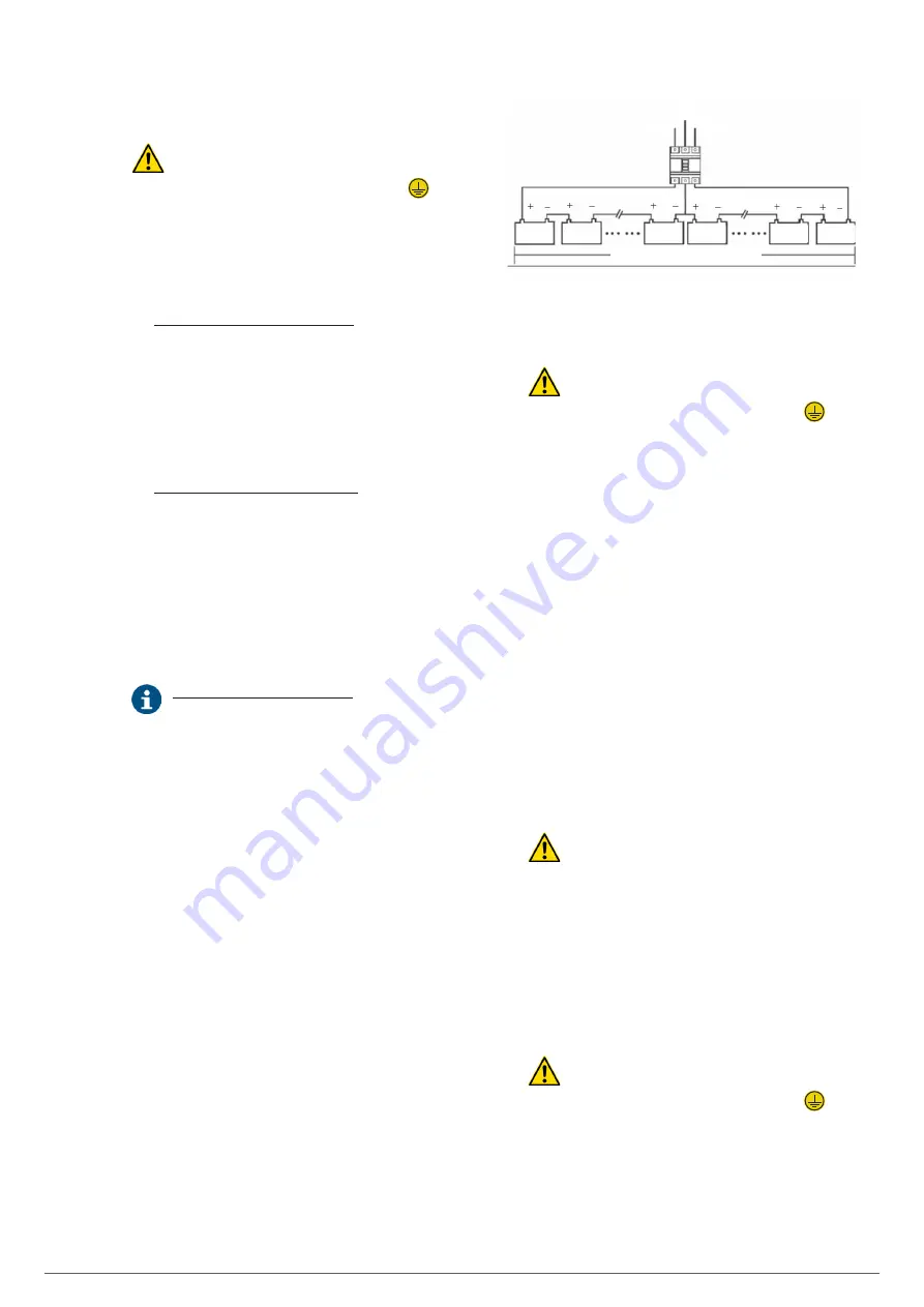
5.5.4. Connection of the battery terminals of the
equipment with those of the battery module.
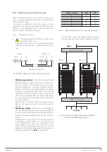
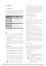
The battery set can be set to 32, 36, 40 or 44 elements con-
nected in serial, but always in even numbers since it is neces-
sary for the internal architecture of the equipment to have a
central point or mid tap -N neutral-. At the same time, the back-
up time together with the power required to feed the loads de-
termines the Ah capacity of the batteries.
Batteries connected in serial
N
BAT –
BAT +
N/2
N/2 +1
N–1
N
2
1
+ N
–
Fig. 27.
Typical connection of battery set.
•
As it is an equipment with protection against class I
electrical shock, it is essential to install the protec-
tive earth conductor to the terminal identified as
. Con-
nect this conductor before supplying voltage to the input
terminals.
•
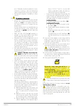
The connection between the terminals of the cabinet or
battery pack and the UPS will always be made through the
supplied cable bundle, respecting the polarity indicated in
the labelling of each unit and the colour of the cables or
their identification at the ends through heat shrink sleeve
(red for positive ‘+’, blue for common 'N' and black for nega-
tive '-').
It is imperative to respect this rule and not to extend the
bundle supplied.
•
For extended back-up time in which more than one module
or battery cabinets are supplied, the connection will always
be in parallel between them and in turn with the equip-
ment. Respect the rule indicated in the previous point for
the connection.
•
For the subracks of 6 slots in parallel will not change the
connection of the batteries with the UPS, since each group
of batteries connects directly with its UPS.
However, there is also another possibility, a set of batteries
inside a cabinet or installed on a rack, common for a sub-
rack system with 6 slots in parallel.
•
Danger of electric shock
. If after starting up the
UPS, it is necessary to disconnect the battery cabinet,
it must carry out a complete shutdown of the equipment.
Open the battery fuse holder switch
(F3)
or the battery dis-
connect switch
(Q8)
located in the accumulators cabinet
and/or the fuse holder switch or disconnect switch
(Q3)
on the UPS.
Wait at least 5 minutes until the filter capacitors have been
discharged.
5.5.5. Earth bonding terminal connection.
•
As it is an equipment with protection against class I
electrical shock, it is essential to install the protec-
tive earth conductor to the terminal identified as
. Con-
nect this conductor before supplying voltage to the input
terminals.
•
Make sure that all loads connected to the UPS are only con-
nected to this ground terminal. Failure to limit the grounding
of the load or loads and the cabinet or battery cabinets to
this single point will create loops back to ground that will
degrade the quality of the power supplied.

