33
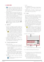
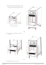
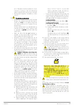
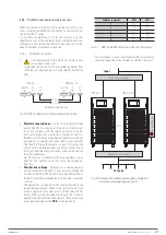
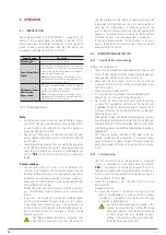
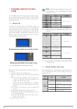
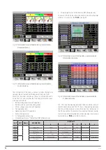
Digital inputs connectors and dry
contacts
SNMP
RS485
RS232
Fig. 32.
Communication connections in 2 and 4 slot models.
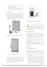
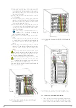
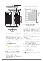
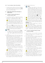
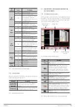
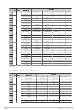
Digital inputs connectors and dry
contacts
RS485
RS232
SNMP
DB15 connectors for the
parallel bus
Fig. 33.
Communication connections in 6 slot models.
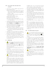
All cables connected to the terminal block of digital inputs
and dry contacts must be twisted cables with double insula-
tion, shielded, and cross-section between 0.5 and 1.5 mm
2
for a
length of between 25 and 50 m.
5.5.7.2. Analogue input of battery and ambient temperature
probes.
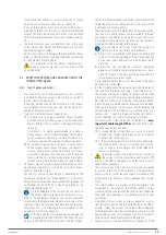
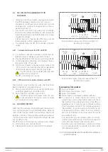
Two connectors are available for the input of external sensors.
One placed in the battery pack and utility to compensate the
floating voltage depending on the temperature of the batteries.
The second optional probe measures the ambient temperature
of the room where it is placed and moves it for reading on the
control panel.
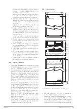
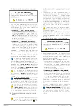
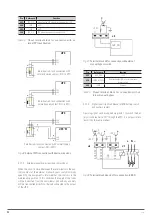
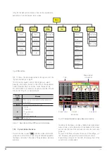
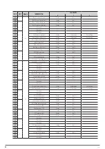
J2
J3
TEMP_BAT
TEMP_ENV
Fig. 34.
Terminal block J2 and J3 for connection the probes.
Pin
Reference
Function
J2-1
TEMP_BAT
Battery temperature probe (floating voltage
compensation)
J2-2
TEMP_COM
Common
J3-1
TEMP_ENV
Ambient temperature probe
J3-2
TEMP_COM
Common
Note:
The probes are designed to be connected to the JP2* and JP3* terminals
are identical (R25=5 Ohm, B25/50=3275). However, one is supplied by default,
which is connected to the JP2* terminals since due to its functionality it
has relevant effects on the batteries. For more information contact our sales
department, the T.S.S. or, failing this, the distributor.
Tabla 3.
Pinout terminal block for temperature probes.
5.5.7.3. Signal input of the remote EPO button (Emergency Stop).
The UPS has the EPO function (Emergency Power Off). This
function can be activated by pressing the button on the control
panel of the UPS and protected by a transparent plastic cover to
avoid unwanted shutdowns or through a remote EPO provided
by the user.
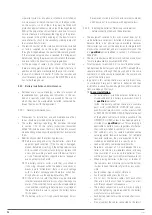
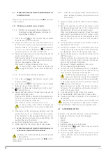
The contacts of the external EPO button are connected to the
JP4 connector, taking into account the following indications of
the adjacent note:
NOTE
:
1.
The action on the EPO button will completely shutdown
the UPS: the rectifier, the inverter and the static bypass.
However, will not disconnect the AC input power source. To
disconnect it is necessary to turn the input circuit breaker
of the protection panel or manual bypass (external of the
equipment) to "Off" position when the EPO is activated.
2.
Terminals 1 and 2 of J4 are factory short circuited with a
jumper. If the remote EPO function is not used, this jumper
will be set and the circuit open between pins 3 and 4. When
connecting an external EPO button, the connection with the
pushbutton itself will be considered.
3.
Regardless of whether you are operating with a single sub-
rack or with several subracks in parallel in the particular
case of 6-slot, points 1 and 2 are applicable on all systems.
For parallel systems, connect the same J4 signal from all
of them and in parallel to the same EPO pushbutton, see
Fig 36.
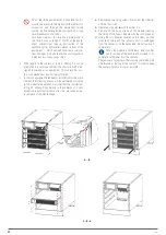
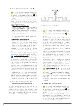
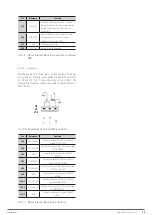
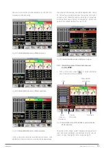
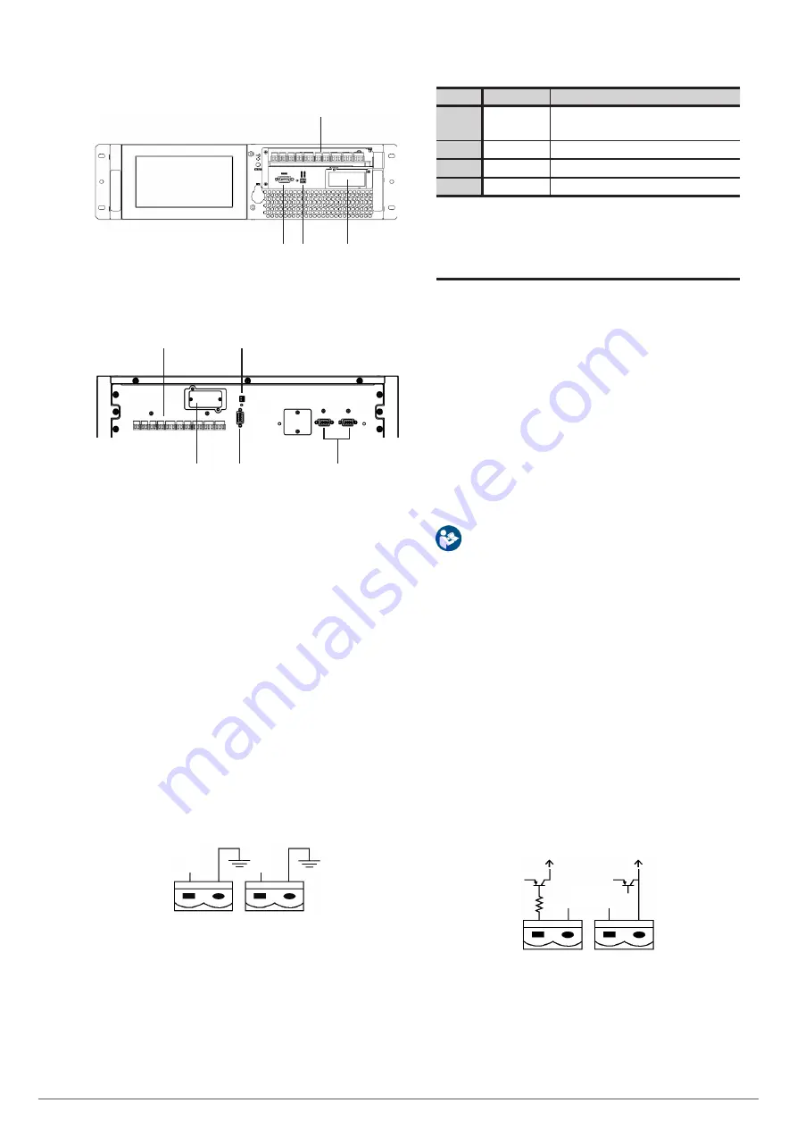
J4
+24 V
EPO_NC
EPO_NO
Fig. 35.
Terminal block J4 for connection with external EPO.
EMi3
SERVOMOTOR VOLTAGE STABILISER
USER'S MANUAL

