34
SALICRU
Pin
Reference
Function
J4.1
EPO_NC
Activating the EPO when disconnecting from J4-2
J4.2
+24V
+24V,
J4.3
+24V
+24V,
J4.4
EPO_NO
EPO activation when connected to J4-3
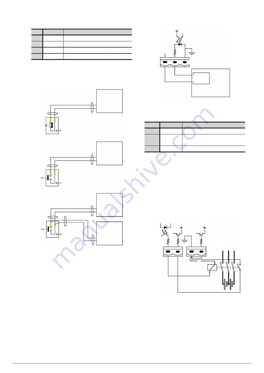
Tabla 4.
Pinout terminal block for connection with ex-
ternal EPO pushbutton.
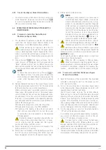
J4-3
J4-4
J4-3
J4-4
J4-3
J4-4
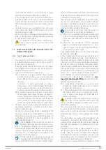
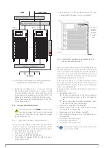
Individual sub-rack connection with
normally open contact -NO- in EPO.
Individual sub-rack connection with
normally closed contact -NC- in EPO.
UPS
J4-1
J4-2
UPS
UPS
UPS 'N'
Parallel sub-racks connection with normally open
contact -NO- in EPO.
Fig. 36.
External EPO connection with device or devices.
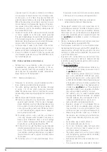
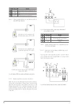
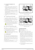
5.5.7.4. External manual bypass auxiliary contact input.
When the circuit is closed between these terminals via the aux-
iliary contact of the external manual bypass switch (normally
open NO), the equipment is informed that the switch is in the
maintenance position. In this condition the supply of the loads
will be direct fed from the commercial grid and any anomaly
will be transmitted directly to the load connected to the output
of the UPS.
J5
+24 V
AUX_NO
Fig. 37.
Terminal block J5 for connection with external
manual bypass switch.
Pin
Reference
Function
J5-1
+24V_DRY
+24V
J5-2
EXTER_BYPASS
Auxiliary contact -NO- of external manual
bypass switch
J5-3
GND
Common
Tabla 5.
Pinout terminal block for connection with ex-
ternal manual bypass.
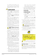
5.5.7.5. Signal shunt trip circuit breaker of BCB battery switch
and auxiliary contact.
A pulsing signal can be supplied via pin J6.1 to switch the bat-
tery circuit breaker to "Off" through the EPO. It is not possible to
rearm it by the same medium.
.
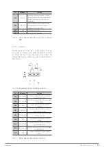
J6
+24 V
BCB_DRV
GND
+24 V
+24 V
J7
+
–
N
BCB_ONL
BCB_CONT
Fig. 38.
Terminal block J6 and J7 for connection to BCB.

