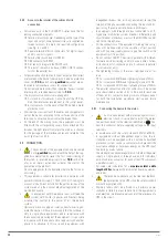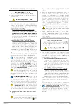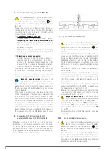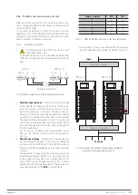
42
SALICRU
7. MONITORING PANEL WITH LCD TOUCH
SCREEN.
This chapter describes the functions and instructions for opera-
tion of the monitoring panel with LCD touch screen, including
detailed information on the menus, warning screens and list of
alarms from the UPS.
7.1. INTRODUCTION.
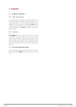
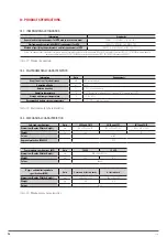
Physically, the monitoring panel with LCD touch screen and
static bypass are part of the same unit as a module, although
they are individual entities with their own functionalities.
Through the LCD panel you can operate and control the UPS,
check all measurements and parameters, equipment status and
batteries, and historical and event logs. The two monitoring
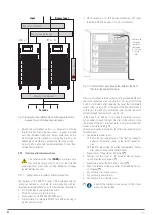
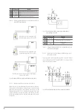
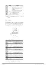
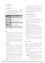
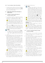
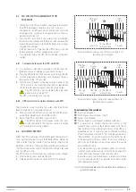
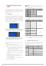
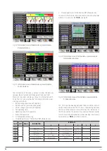
panels available are shown in Fig. 41
Monitoring panel installed in sub-racks of 2 and 4 slots.
Monitoring panel installed in the sub-rack of 6 slots.
Fig. 41.
Monitoring panels with LCD touch screen.
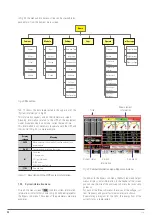
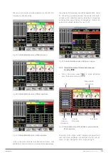
Basically the LCD monitoring panel is divided into three func-
tional areas:
•
LCD touch screen with structured menus.
•
Flowchart of power LEDs and "Status" indicator and audible
alarm.
The flowchart is only available in the sub-racks of six
slots and it is information that appears replicated in the
"Cabinet" menu of the touch screen.
Additionally each power module has its own energy
flowchart, but obviously without the bypass and output
indicators.
The "Status" LED and acoustic alarm are present in all
sub-racks.
•
EPO emergency stop push button and function keys.
The EPO push button with the protective cover is avail-
able on all equipments.
The BYP, INV, and MUTE shortcut keys are only avail-
able in six-slot sub-racks.
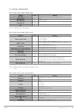
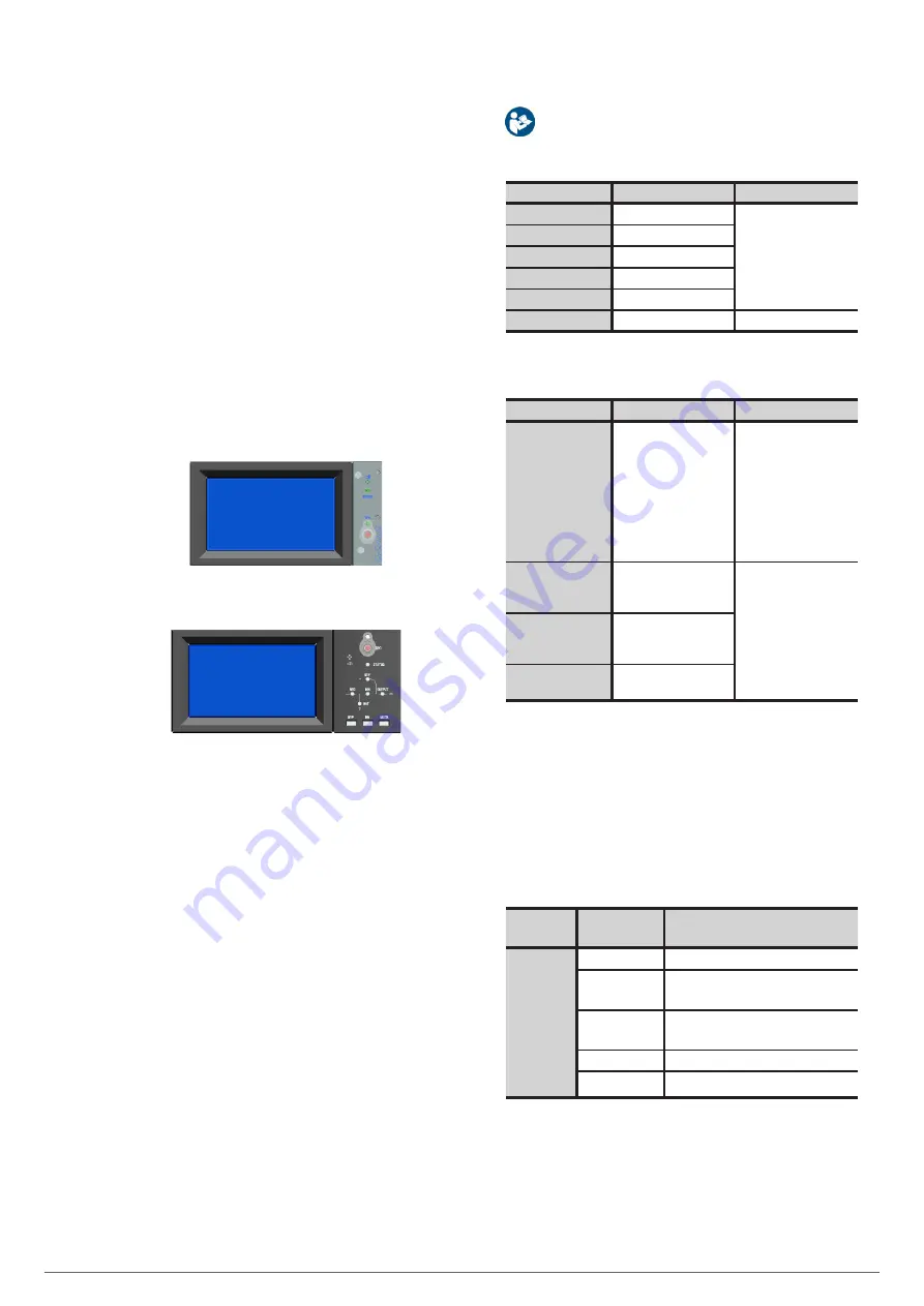
For further information see Tab. 12.
NOTE:
The data and values presented in this document
are mere examples, so they will be different from those
displayed on your unit.
Indicator
Function
Availability
REC
Rectifier
In 6-slot sub-racks
BAT
Batteries
BYP
Bypass
INV
Inverter
OUTPUT
Output to loads
STATUS
Status
In all sub-racks
Tab. 12.
Functionality and availability of the LEDs in the
sub-rack.
Operation keys
Function
Availability
EPO
Emergency power off
breaks the load power for
the rectifier, the inverter
and the static bypass. If
battery protection with
shunt trip is available, the
battery power is also cut
off by acting on the shunt
trip mechanism.
In all sub-racks
BYP
Shortcut key for
transferring from Normal
Mode to Bypass Mode
In 6-slot sub-racks
INV
Shortcut key for
transferring from Bypass
Mode to Normal Mode
MUTE
Key to silence the audible
alarm
Tab. 13.
Functionality and availability of the push buttons
on the sub-rack.
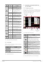
7.2. DIAGRAM OF ENERGY FLOW TO LEDS.
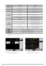
The operating mode of the equipment is represented by the
LEDs of the energy flow. The status description of the LEDs is
shown in Tab. 14.
LED
indicator
Status
Description
RECT -
Rectifier
Green
Rectifier operation, correct on all modules.
Flashing Green
At least one of the rectifiers of the modules
is starting up.
Red
At least one of the rectifiers of the modules
is failing.
Flashing Red
The input of at least one module is wrong.
Off
Rectifier does not work.

