43
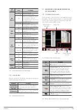
LED
indicator
Status
Description
BAT -
Batteries
Green
The battery is charging.
Flashing Green
The battery is being discharged.
Red
Batteries are wrong (battery fault, battery
or inverted batteries) or the battery
converter is abnormal (fault, over current or
over temperature), EOD.
Flashing Red
Low battery voltage.
Off
Batteries and battery converters are
correct, batteries are not being charged.
BYP -
Bypass
Green
Output supply from the Bypass
Red
Bypass module fault or static bypass
switch fault.
Flashing Red
Wrong Bypass voltage.
Off
Bypass voltage is correct, but the Bypass
module does not work.
INV -
Inverter
Green
The inverter is feeding the load.
Flashing Green
Inverter starting, synchronizing or UPS
operating in ECO Mode - Standby -.
Red
At least one inverter of a module is failing.
The inverter does not supply voltage to the
load connected to the output.
Flashing Red
At least one inverter of a module is failing.
The inverter supplies voltage to the load
connected to the output.
Off
The inverter is not running on all modules.
OUTPUT -
Load
Green
The UPS is supplying output voltage and
is correct.
Red
Short circuit at the output, no output or
maximum output overload time exceeded.
Flashing Red
Output overload
Off
No output voltage
STATUS -
Status
Green
Correct operation.
Red
Fault.
Tab. 14.
Description of the Led indications.
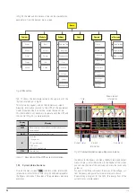
7.2.1. Acoustic alarm.
The acoustic alarm of the UPS has two tones that can be acti-
vated during operation, see Tab. 15.
Modulation
Availability
Two short beep,
followed by one
long beep
Indicates that the system is in a status of general
alarm (for example when there is an input mains
failure).
Continuous beep
Indicates that the system is in a status of urgent alarm
(for example fuse blown up or system fault).
Tab. 15.
Acoustic alarm tones.
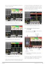
7.3. DESCRIPTION OF THE SCREENS SHOWN ON THE
LCD TOUCH SCREEN.
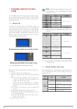
7.3.1. Start menu or main screen.
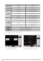
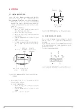
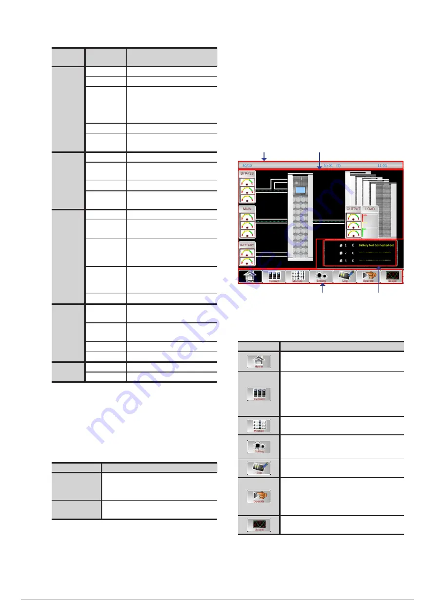
The main screen is shown in Fig. 42 as an example that can be
displayed on the LCD monitoring panel. It is basically divided
into four areas: System information, Power flow, Current warn-
ings or Alarm window, and Main menu.
Information bar of
the system
Energy flow
Main menu
Current warnings
or alarms
Fig. 42.
Home screen or main screen.
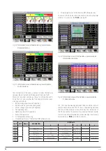
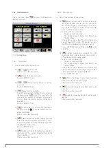
Icon
Description
Main screen:
Return to the main menu page.
System information:
Bypass, main, output (voltage,
current, power factor, frequency), battery information
(capacity, remaining time, days worked in this mode,
battery temperature, ambient temperature) information
on the load (percentage of active, reactive load, apparent
load).
Information of the power modules:
input, output, load,
S-code, module information).
Configuration:
Date and time, language, communications,
user (password 1), selection of batteries, selection of
service, selection of parameters, configuration.
Data logger:
It shows the events that have occurred.
Actions regarding the system:
Mute ON/OFF, clear
fault, transfer to bypass, transfer to inverter, allow module
“Off”, reset historical data of batteries, restart time of use
of dust filters, batteries’ test, maintenance of batteries,
recharge boosting of batteries, float batteries, stop test.
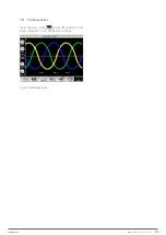
Waveforms:
Oscillogram of the output voltage, output
current, bypass voltage.
Tab. 16.
Description of the home or main menu icons.
EMi3
SERVOMOTOR VOLTAGE STABILISER
USER'S MANUAL

