44
SALICRU
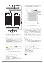
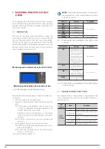
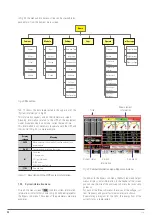
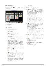
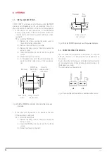
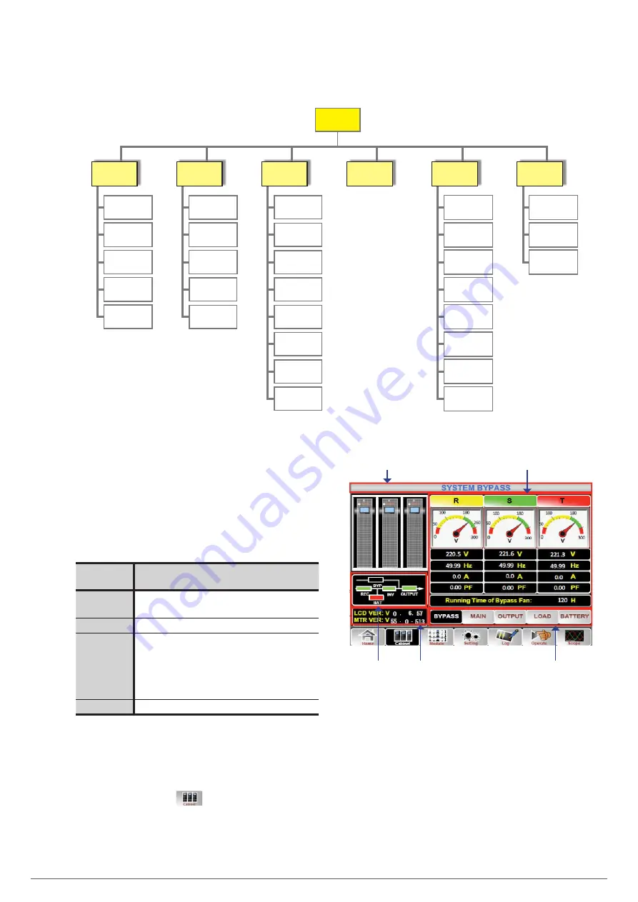
In Fig 43 the menu and sub-menus tree can be checked in ex-
panded form from the home or main screen.
Bypass
Mains
Output
Charge
Battery
Input
Output
Charge
Info.
S-code
Silence
Delete
Transfer to
Bypass
Transfer to
Inverter
Battery test
Battery
maintenance
Boosting of
batteries
Floating of
batteries
Output voltage
Output current
Bypass voltage
Date and Time
Language
Communication
User
Batteries
Service
Values
Configuration
Home
Cabinet
Module
Settings
Logs
Operate
Oscilloscope
Fig. 43.
Menu tree.
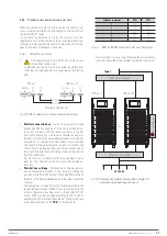
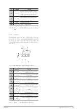
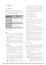
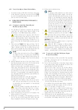
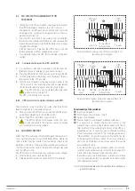
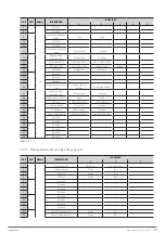
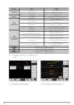
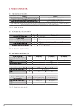
Tab. 17 shows the data represented in the upper bar of the
"System Information" in Fig. 42.
This information appears only on the [Home] main screen.
Grouping information related to the UPS of the equipment
model, module numbers, unit mode, current date and time.
This information is not necessary to operate with the UPS and
that shown in Fig. 42 is a mere example.
Display
contents
Meaning
40/10
Maximum power system with all installed modules / unit
power module
N = 01
1 power module installed in the system
(S)
Unit mode.
S: A single unit.
P-0/1: parallel mode.
E: ECO mode.
PE-0/1: ECO parallel mode.
11:03
Date and time
Tabla 17.
Description of the UPS system information.
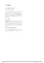
7.3.2. System information menu.
Click on the menu screen
to obtain system information.
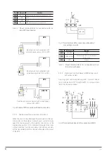
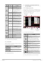
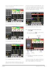
Information similar to that shown in Fig. 44 will be displayed for
the Bypass sub-menu. The values of the parameters are mere
examples.
Title
Measurement
information
Version
information
Sub-menu
Current status
Fig. 44.
Cabinet information menu. Bypass sub-menu.
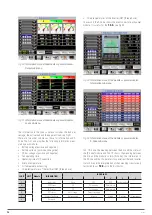
In addition to the Bypass sub-menu, the Main input and Output
menus display similar information. In the header of the screen
you can see the title of the analysed sub-menu that we use to
guides us.
For each of the three sub-menus the values of the voltage, cur-
rent, frequency and power factor parameters are shown.
By emulating a diagram for the LEDs, the energy flow of the
current status is represented.

