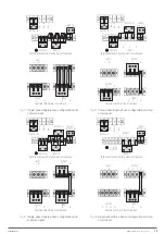
5
2. SAFETY INFORMATION.
2.1. USING THIS MANUAL.
The documentation of any standard equipment is
available to the customer on our website for download
(www.salicru.com)
.
•
For equipment “powered by socket”. This is the intended
portal for obtaining the user manual and safety instructions
EK266*08.
•
For equipment "with permanent connection", connection to
terminals. Although it can be downloaded from the web-
site, a CD-ROM or Pen Drive can be delivered with the UPS
with all the necessary information for its connection and
commissioning, including EK266*08 safety instructions.
Before carrying out any action on the equipment relating to its
installation or commissioning, change of location, configuration
or manipulation of any kind, you must read the safety instruc-
tions carefully.
The purpose of the user manual is to provide information re-
garding safety and explanations of the procedures for installa-
tion and operation of the equipment. Read them carefully and
follow the steps indicated in the order established.
Compliance with the "Safety Instructions" is
mandatory and the user is legally responsible
for
compliance and enforcement.
The equipment is delivered properly labelled for the correct
identification of each of the parts, which together with the in-
structions described in this user manual allows the operations
of installation and commissioning to be performed in a simple
and orderly manner without having any doubts whatsoever.
However, because the product is constantly evolving,
discrepancies or slight contradictions may arise. If in
any doubt, the labelling on the equipment itself will al-
ways prevail.
Finally, once the equipment is installed and operating, it is rec-
ommended to save the documentation downloaded from the
website, CD-ROM or Pen Drive in a safe and easy-to-access
place, for any future queries or doubts that may arise.
When a system differs from that shown in the figures in
Section 4, except when the number of modules con-
nected in parallel and/or the technical specifications
are modified, additional explanatory annexes will be
edited if deemed appropriate or necessary. These will
usually be printed on paper.
This user manual is useful for
SLC ADAPT X
subrack equip-
ment, with the following configurations:
•
Model with two slots. It allows the installation of one or
two modules.
•
Model with four slots. It allows the installation of between
one and four modules.
•
Model with six slots. It allows the installation of between
one and six modules and is parallelable in turn with five
subracks.
Conceptually, they are designed to be assembled into a 19“
rack cabinet, whether they share the batteries or not.
While the customer can perform these adaptations on their
own or otherwise, we can also manufacture any configuration
on demand.
For those systems shipped from the factory and assembled in a
rack cabinet, we have the supplementary and generic EL096*00
document in which the parts (connection terminals, switching
mechanisms, etc.) and the corresponding operations are identi-
fied.
The following terms are used interchangeably in the document
to refer to:
•
“
SLC ADAPT X, ADAPT X, ADAPT, UPS, system, equip-
ment or unit.
”.- Uninterruptible Power Supply ADAPT se-
ries of subfamily X.
Depending on the context of the phrase, it can refer either
to the actual UPS itself or to the the UPS and the batteries,
regardless of whether it is all assembled in the same metal
casing - box - or not.
•
“Batteries or accumulators”
.- Group or set of elements
that stores the flow of electrons by electrochemical means.
•
“
T.S.S.
”.- Technical Service and Support.
•
"
Client, installer, operator or user
".- These are used
interchangeably and by extension to refer to the installer
and/or operator who will carry out the corresponding ac-
tions, and the same person may be responsible for carrying
out the respective actions when acting on behalf of, or in
representation of, same.
2.1.1. Conventions and symbols used.
Some symbols may be used and appear on the equipment, bat-
teries and/or in the context of the user manual.
For more information, see section 1.1.1 of document EK266*08
on
"Safety instructions"
.
In the event that there are differences in relation to the safety
instructions between document EK266*08 and the user's
manual of the equipment, the latter will always prevail.
2.1.2. Safety considerations.
•
While the security-related considerations will be dealt with
in more detail in Section 5, the following will be taken into
account:
Inside the battery cabinet there are accessible parts
with HAZARDOUS VOLTAGE and consequently risk of
electric shock, so they are classified as RESTRICTED
ACCESS ZONES. Therefore, the key of the battery cab-
inet will not be available to the OPERATOR or USER,
unless such person has been properly instructed.
In case of intervention inside the battery cabinet either
during the connection, preventive maintenance or re-
pair procedure, it will be taken into account that
the
voltage of the battery set exceeds 400 V DC
and
consequently safety measures must be taken.
Any operation of connecting and disconnecting the
cables or handling inside a cabinet will not take place
for around 10 minutes in order to allow the internal
discharge of the capacitors of the equipment. Even so,
check with a multimeter that the voltage at terminals is
less than 36 V.
In case of installation in neutral IT mode, the switches,
circuit breakers and thermal magnetic protection must
cut the NEUTRAL in addition to the three phases.
EMi3
SERVOMOTOR VOLTAGE STABILISER
USER'S MANUAL

