13
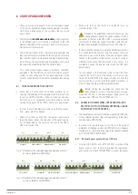
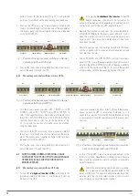
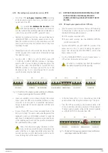
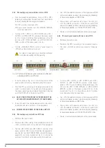
The auxiliary terminals of the UPS are identified as follows,
depending on the product series:
ADAPT, ADAPT-X, pins
1
and
2
of
(JP5)
.
ADAPT2, pins 1 and 2
(IDIG3)
.
CUBE3+, 2-terminal strip
(X51)
.
CUBE4, 2-terminal strip
(IDIG3)
.
X-PERT, terminals
(X10-1), (X10-2)
.
X-TRA, terminals
(MBY-1)
and
(MBY-2)
.
TWIN PRO, 2-terminal strip
(EMBS)
.
•
The way to connect the UPS control cables to the panel will
vary depending on its series, as will the number of termi-
nals available on the control strip:
CUBE3+ and CUBE4.
Make the parallel connection between the auxiliary
contacts of the manual bypass switch on each unit and
those on the bypass panel (see Fig. 5 and 7).
ADAPT, ADAPTX, pins 1 and 2 of JP5, ADAPT2, pins 1
and 2 of IDIG3, TWIN PRO2, X-TRA and X-PERT.
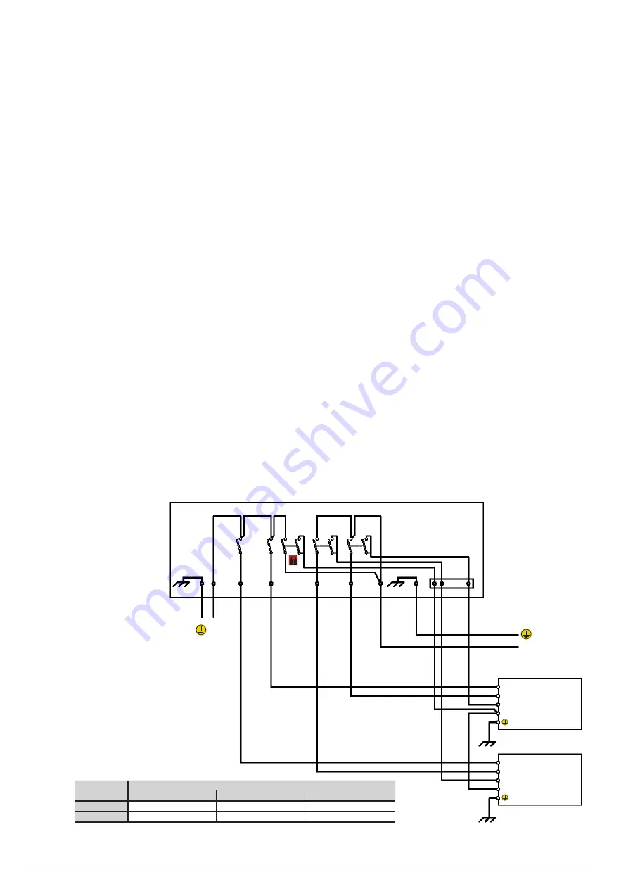
The manual bypass switch on the panel will have as many
auxiliary contacts extended to the control strip as numbers
of UPSs to be connected in parallel (see Fig. 6 and 8).
Connect the terminals of the panel strip to each UPS
of the parallel system respectively. These connections
must never be joined
, as internally, each UPS has dif-
ferent masses.
As stated earlier, this connection is a safety lock against
unwanted or erroneous operations.
INPUT LINE
LOADS OUTPUT
MANUAL
BYPASS
(*) Aux. cont.
Manual Bypass
(1)
UPS 1 Output
(2)
•••
UPS "N" Output
(2)
UPS 1 INPUT
INPUT
OUTPUT
Aux. cont. output
Aux. cont. manual bypass
MANUAL
BYPASS PANEL
UPS
"
N
"
UPS
"
N
"
INPUT
UPS 1 OUTPUT
UPS
"
N
"
OUTPUT
•••
UPS 1
UPS 1 INPUT
UPS
"
N
"
INPUT
INPUT
OUTPUT
Aux. cont. output
Aux. cont. manual bypass
•••
•••
UPS
"
N
"
OUTPUT
UPS 1 OUTPUT
•••
•••
(*) Aux. cont.
(*) Aux. cont., available on manual bypass panels for these UPSs:
SLC CUBE 3+
SLC CUBE 4
SLC TWIN PRO 2
(1)
YES
YES
-
(2)
YES
YES
-
Fig. 5.
Manual bypass panel for “n” standard parallel or redundant UPSs, for UPS series CUBE3+, CUBE4 and TWIN PRO 2.
5.3.7.3. Connection between the auxiliary contact of the
output switch on each UPS and those of the bypass
panel (only available on panels from the SLC CUBE3+,
SLC CUBE4, SLC X-PERT and SLC X-TRA series).
The output switch on each UPS has a normally open auxiliary
contact with a cable connected as a bridge
(PT)
that closes its
circuit respectively on terminal strip
(X45)
on CUBE3+, on ter-
minal strip
(IDIG4)
on CUBE4 30-80 kVA, between the terminals
on strip
(XAUX-1)
and
(XAUX-2)
on X-TRA, or between termi-
nals
(X10-5)
and
(X10-6)
on X-PERT.
On CUBE4 7.5-20 kVA models, the output switch does not have
an auxiliary contact, but it does have the auxiliary contact signal
of the external output switch between terminals 5 and 11 or 9 on
the INPUT SIGNAL terminal strip. .
•
Remove it on each unit and, using control cables (minimum
1 mm
2
and maximum 2.5 mm
2
), connect the terminals identi-
fied as “OUTPUT AUXILIARY CONTACT” on each UPS
(X45)
,
(IDIG4)
, (between terminals
5 and 11 or 9 INPUT SIGNAL)
,
(XAUX-1)
and
(XAUX-2)
or
(X10-5)
and
(X10-6)
to the re-
spective terminals on the manual bypass panel, paying at-
tention to the correlative order of each one.
That is to say, the “OUTPUT AUXILIARY CONTACT” terminals
(X45)
,
(IDIG4)
, (between terminals
5 and 11 or 9 INPUT
SIGNAL
),
(XAUX-1)
and
(XAUX-2)
or
(X10-5)
and
(X10-6)
on
UPS no. 1 to the terminals on auxiliary strip “OUTPUT 1 UPS”,
the “OUTPUT AUXILIARY CONTACT” terminals
(X45)
,
(IDIG4)
,
(between terminals
5 and 11 or 9 INPUT SIGNAL
),
(XAUX-1)
and
(XAUX-2)
or
(X10-5)
and
(X10-6)
on UPS no. 2 to the termi-
nals on auxiliary strip “OUTPUT 2 UPS” and so on according to
the number of units that make up the system.
USER'S MANUAL
Summary of Contents for SLC ADAPT
Page 2: ...2 SALICRU...
Page 21: ...21 USER S MANUAL...


