15
series.
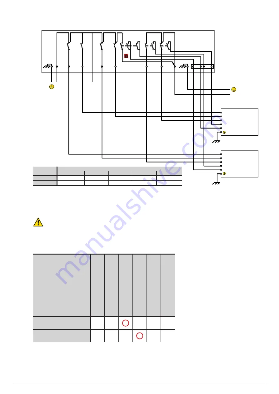
INPUT LINE
LOADS OUTPUT
INPUT
STATIC BYPASS
OUTPUT
Aux. cont. output
Aux. cont. manual bypass
MANUAL
BYPASS PANEL
UPS
"
N
"
UPS 1 OUTPUT
UPS
"
N
"
OUTPUT
UPS 1
UPS 1 INPUT
UPS
"
N
"
INPUT
INPUT
STATIC BYPASS
OUTPUT
Aux. cont. output
Aux. cont. manual bypass
•••
•••
•••
MANUAL BYPASS
Aux. cont.
UPS 1 Manual Bypass
(1)
•••
UPS "N" Manual Bypass
(1)
UPS 1 Output
(2)
•••
UPS "N" Output
(2)
ST
ATIC BYP
ASS
INPUT LINE
UPS
"
N
"
ST
ATIC BYP
ASS
UPS 1 ST
ATIC BYP
ASS
•••
UPS
"
N
"
OUTPUT
UPS 1 OUTPUT
•••
UPS 1 ST
ATIC BYP
ASS
UPS
"
N
"
ST
ATIC BYP
ASS
•••
UPS 1 INPUT
UPS
"
N
"
INPUT
•••
(*) Aux. cont.
(*) Aux. cont., available on manual bypass panels for these UPSs:
SLC ADAPT
SLC ADAPT-X
SLC ADAPT2
SLC X-PERT
SLC X-TRA
(1)
YES
YES
YES
YES
YES
(2)
YES
YES
YES
(1)
YES
YES
(1) The IDIG4 input must be programmed as an auxiliary contact for the NC output circuit breaker.
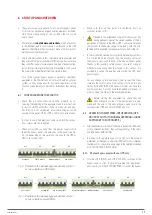
Fig. 8.
Manual bypass panel for “n” standard parallel or redundant UPSs with a separate bypass line, for the ADAPT,
ADAPT-X, ADAPT2, TWIN , X-PERT and X-TRA series.
Note
1
In the SLC ADPAT2 series, the IDIG3 digital input is normally configured as an auxiliary contact input for the manual bypass
circuit breaker. The IDIG4 digital input, on the other hand, is not normally programmed, meaning that for parallel configuration, it must
be configured as an auxiliary disconnector input for the NC output circuit breaker.
So, the suitable configuration of digital inputs for a parallel system will be:
Genset Input
Shutdown Input
Maintenance Bypass Input
Output Auxiliary Contact Input
Battery Circuit Breaker Auxiliary Contact Input
External Digital Input
SREG_INP_DIG_IN3_
BOOLSET
0
0
1
0
0
0
SREG_INP_DIG_IN4_
BOOLSET
0
0
0
1
0
0
USER'S MANUAL
Summary of Contents for SLC ADAPT
Page 2: ...2 SALICRU...
Page 21: ...21 USER S MANUAL...


