28
SALICRU
The fuses will be supplied in a plastic bag inside the
battery cabinet or inside the rack cabinet in case of
adaptations, except the fixed ones, since they form a
mechanical part of the cabinet.
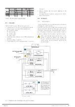
The size of the protection fuses and switches are di-
mensioned according to the initial start-up power.
Any modification (addition or reduction of in-
stalled modules) will necessarily involve the
revision and/or adaptation
of the installation (cable
sections, protection sizes, etc.).
In the same way, it is recommended to enlarge the bat-
tery pack in case of power amplification to maintain the
back-up time as much as possible.
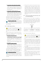
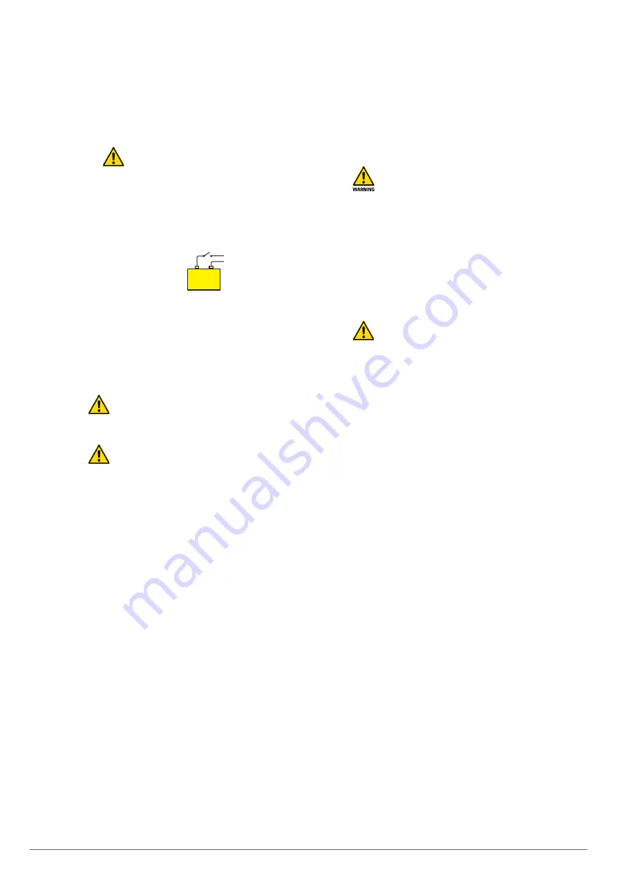
The original factory battery circuit is open.
– +
Activate the disconnector and/or place the fuses
in the corresponding fused isolator switch and
set to
“On” once the UPS has been started. The front panel
indicates that the batteries are not connected and that
that the number of batteries in series in each branch
has been verified to be equal and to match the number
of batteries in series configured in the UPS.
•
Do not operate the battery fuse holder switch and/
or the disconnect switch when the device is running.
In units manufactured by us, these mechanisms
are not
load-disconnect types
.
•
When a unit or a parallel system is expected to be
out of service for an extended period of time, a com-
plete stop must be carried out beforehand and the 3 fuses of
the fused isolator switch of the device or the battery module
shall be removed for safety and stored in a safe place.
5.4.3. Access to the interior of the cabinet for its connection.
•
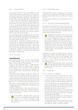
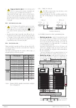
All devices in the SLC ADAPT2 series have the following
connection elements:
Terminal block for power. Depending on the type of input
and output, they are supplied with some connection
strips between terminals to obtain the required configu-
ration (see
to in Annex I
).
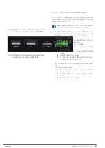
Separate terminal block connectors for digital inputs
and dry contacts signals.
Terminal block connector for RS485.
DB9 connector for RS232.
Slot prepared to integrate the SNMP card.
The 6-slot cabinets also have HDB15 / DB15 connectors
for the parallel bus.
•
All power connection terminals (input, output and batteries)
are located on the back of the devices, behind a protective
cover. Only
T.S.S.
personnel or
qualified
personnel are au-
thorised to remove these covers for connection.
Do not remove more covers than indicated. Access to other
internal parts is reserved exclusively for
T.S.S.
•
The dry-contact connectors are located on the front of the
UPS.
•
Consider the cross section of the cables and crimped termi-
nals at their ends, in relation to the surface and size of the
terminals, to obtain optimum contact between them.
•
At the end of the wiring tasks, the device must be fitted
with the corresponding lids firmly attached.
5.5. CONNECTIONS.
•
The connection of the device can only be carried out
by
qualified
personnel with the help of the supplied
documentation, however the first start-up of the system is
reserved exclusively to our
T.S.S.
or distributor, as an im-
plicit action that activates the start of the guarantee of the
product .
Do not apply power to the device before the first start-up.
•
This device is suitable for installation in networks with
power distribution system TT, TN-S, TN-C or IT, taking into
account at the time of installation the particularities of the
system used and the national electrical regulation of the
destination country.
•
In devices with three-phase input will feed the
system with 4 wires (3 phases and Neutral), being
essential the neutral in the power of all three-phase system.
Optionally we can supply an isolation transformer to gen-
erate the neutral, in those mains supply that do not have it.
Only in single-phase devices and in compliance with the
rated supply voltage of the device, it is possible to dispense
with the neutral and to replace it with another phase in
its absence. In this case and in devices with independent
bypass line, as in any equipment, respect the order of the
phases when connecting the input and bypass, using the
same pair of phases in both networks.
•
In devices with three-phase input connected to an IT-type
power distribution system, breakers, differentials and mag-
netothermal protections must cut the NEUTRAL in addition
to the three phases.
•
All the connections of the device including the control ones
will be done with all the switches at rest position and with
no power supply (power supply line switch of the device in
«Off» position).
•
Do not connect ADAPT2 devices in parallel with different
firmware versions, settings and/or back-up times. Follow
all instructions related to parallel connections to connect
up to 5 cabinets in parallel (6-slot cabinets only).
•
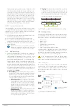
The tightening torques of the screw terminals are as fol-
lows:
For screw with M6 thread, tightening torque of 5 Nm.
For screw with M8 thread, tightening torque of 13 Nm.
For screw with M10 thread, tightening torque of 25 Nm.
•
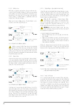
The parallel connection of 6-slot cabinets shall be carried
out as described in sections 5.5.1 to 5.5.5 individually for
each cabinet, and is subject to having its manual bypass
board for the installation procedure as well as for start-up
and future maintenance.


