22
SALICRU
MANUAL BYPASS
AC OUTPUT
BYPASS
STATIC
SWITCH
INVERTER
BATTERY
CHARGER
BATTERY PACK
AC INPUT
BYPASS
LINE
RECTIFIER-BOOSTER
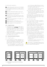
Fig. 13.
Block diagram of UPS stopped, with no power
flow, without powering the loads yet (typically in
initial startup).
MANUAL BYPASS
AC OUTPUT
BYPASS
STATIC
SWITCH
INVERTER
DC-LINK
BATTERY
CHARGER
BATTERY PACK
AC INPUT
BYPASS
LINE
RECTIFIER-BOOSTER
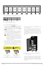
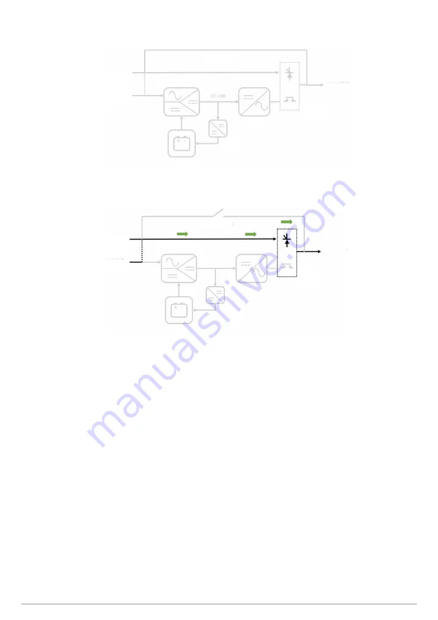
Fig. 14.
UPS power flow stopped (but supplying the loads
via the bypass).
4.5.1. Normal mode.
For the UPS to work in normal mode, there must be an input
network (input switch activated), output switch activated
(supply for the loads), and there must be batteries in the unit or
connected in an external cabinet.
In this double conversion mode, the rectifier is powered by
the AC network, supplying direct voltage to the inverter (DC
bus). The inverter converts the DC voltage into a stabilised sine
wave, connecting to the loads via its static switch. The rectifier
also supplies voltage to the battery charger, which keeps the
batteries in an optimal state of charge.
It is the operating status with the highest protection for the
loads, as it applies "clean" voltage to them independently of the
input voltage, and with the battery power available in case an
AC network fault occurs.


