42
SALICRU
6. OPERATION
This section describes the basic procedures for starting the
UPS, with start-up being understood as reaching the normal
operating mode described in section 4.5, specifically in "4.5.1
Normal mode". That is, "online" or double conversion mode, to
achieve maximum protection for critical loads.
Additional procedures are also described, understanding that
these should only be carried out exceptionally due to a unit
shutdown, maintenance, changes in the installation, faults, etc.
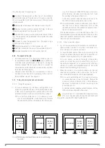
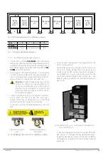
All procedures will consider an installation whereby there is a
control panel that is external to the UPS, highly recommended
for facilitating interventions and maintenance, equipped with
the following:
•
Switch for UPS input voltage.
•
Switch from the UPS output to the loads.
•
Switch corresponding to the UPS maintenance bypass, with
its auxiliary contact wired to the corresponding terminal
(
IDIG3
see
•
Optionally, on units with a separate static bypass line, a
switch for this line is also present on the panel.
6.1. UPS START-UP
6.1.1. Checks before start-up
Read the technical documentation
Before isolating and starting the unit, all instructions
contained in this manual and in the technical support documen-
tation must be read and understood.
Before starting the unit:
•
Make sure that all connections have been made correctly
and with sufficient torque, observing the unit's labelling
and the instructions in chapter 5.
•
Check that the unit's Input, Bypass and Output disconnect
switches/switches and the control panel external to the
UPS are in the "Off" position.
•
Check that the internal battery disconnect switch and/or
the external cabinet are in the "Off" position.
•
Make sure all loads are switched off (set to "Off").
•
It is very important to proceed according to the order estab-
lished in the following procedures of this section.
•
Before starting the unit, check that: All installation and
electrical connection tasks have been carried out by duly
qualified technicians.
•
All power and control cables have been connected correctly
and firmly to the corresponding terminals.
•
With regards to external boards or panels, it is very impor-
tant to wire the auxiliary contact of the maintenance by-
pass switch, and the auxiliary contact of the output switch
for parallel systems, to the corresponding connector of the
unit.
•
The earth cable is connected correctly.
•
The battery polarity is correct and the voltage is within the
operating values.
•
The phase rotation (phase sequence) of the AC input line
is correct and the voltage is within the tolerance of the op-
erating values. The same applies for the separate bypass
line, if any.
•
The emergency stop circuit (EPO), if installed, is not acti-
vated (a wire bridge is supplied in the unit, connected by
default to the terminals of this connector, which allows
normal operation).
6.1.2. Initial start-up
The initial start-up of the UPS after reception and installation
has certain specificities. For normal or periodic start and stop
operations, refer to sections
The initial start-up must be carried out by authorised
staff (
T.S.S.
or the distributor). This operation activates
the start of the product's warranty, and as well as the start-up,
the qualified technician will also carry out additional checks
and calibrations "in-situ" that are not described in this manual.
Once all checks described in
have been carried out, pro-
ceed to:
1.
Check, once again, the correct connection of the
phases and neutral
to the unit's input, as well as that of
the separate static bypass line, if any. In the event of incor-
rect connection or phase rotation, correct it.
2.
Supply general voltage to the control panel external
to the UPS.
3.
Set the switch corresponding to the UPS input on the
control panel to "On".
4.
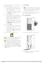
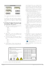
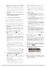
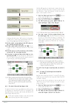
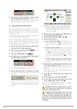
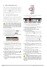
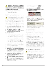
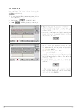
Set the input switch of the UPS to "On" (Q1). The "Initial
Settings" screen appears
, see
initial start-up of the UPS. Otherwise, the unit is already
configured according to the installation and you can refer
Initial Settings
NEXT
Language
ENGLISH
3x400 V
Auto-50 Hz
September
9
4
2021
0
Unit Nominal Voltage
Nominal Frequency
Hour
Day
Year
Minute
Month
Date & Time
Fig. 51.
First configuration screen for initial start-up.


