48
... also an audible alarm will beep in each equipment with the
message in the screen and the affected UPS/s will not be able to
be started up, due to the wrong bypass phase rotation.
If it happens in only one UPS of the parallel system, turn
«Off» the bypass switch
(Q4a)
of the corresponding equip-
ment and the one in the switchgear panel board. Swap two
phases of the bypass terminals of the UPS leaving the con-
nections in the same order as the rest of the equipments and
repeat the start up procedure described in the three previous
steps.
If it happens in all equipments of the parallel system, turn
«Off» the bypass switch
(Q4a)
of each UPS and bypass
switches of the switchgear panel board, swap two phases
in the bypass terminals of the switchgear panel and repeat
the start up procedure described in the three previous steps
up to now.
• At this point, with no active alarm, green LED of Input Voltage
OK
(a)
(see Fig. 40), should light in all UPSs.
• Start up the inverter, by means of the keypad
(3)
(see Fig. 40). In
parallel systems make the procedure equipment by equipment
the first time or after complete shutdown, in order to establish
the communications among each unit of the system.
From main screen press
(
)
key to access to «CONTROL AND
STATUS OF THE UNIT» submenu (screen 1.0), and then press
(
)
key. The screen 1.1 will be displayed, asking you to start the
equipment up by pressing
(ENT)
. Do so, and then validate the
operation by pressing
(ENT)
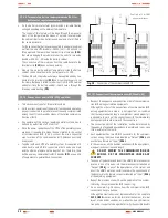
again. See the diagram of Fig. 39.
CONTROL
&
STATUS
OF THE UNIT
UPS ON STAND-BY
<ENT> TO START
<ENT> TO CONFIRM
<ESC> TO CANCEL
UPS RUNNING
<ESC> TO STOP
<ENT> TO CONFIRM
<ESC> TO CANCEL
BATTERY TEST
<status>
screen 1.0
screen 1.1
screen 1.2
screen 1.3
screen 1.4
screen 1.5
(ENT)
(ENT)
(ESC)
(
)
(
)
(
)
(
)
Screens 1.1 and 1.3 are alter-
nated in the diagram, depen-
ding on the status of the equipment.
The same happnes with the screens1.6
and 1.8. Depending on the Smart Eco-
mode status, they are swapped.
SMART ECO-MODE
<ENT> TO ACTIVE
<ENT> TO CONFIRM
<ESC> TO CANCEL
SMART ECO-MODE
<ESC> TO DEACTIVE
<ENT> TO CONFIRM
<ESC> TO CANCEL
screen 1.6
screen 1.7
screen 1.8
screen 1.9
(ENT)
(ENT)
(ESC)
(
)
(
)
(ESC)
(ENT)
(ENT)
(ESC)
(ESC)
(ESC)
Fig. 39.
Diagram, start up/shutdown procedure.
• After about 30 seconds, the inverter and rectifier of the UPS
or each UPS will be running, but not supplying output voltage
because their respective switches
(Q2)
of the equipment and
panel board are still turned off.
In parallel systems, the first UPS starting the inverter will be the
one set as «Paral. Mst. Byp», the one with the highest address as
«Paral. Slv. By.Rsv» and the rest ones, if any as «Paral. Slv. By».
Logically, in parallel systems of two UPS units there will not be
any «Paral. Slv. By».
•
Parallel equipments only.
To check the hierarchy of the UPSs (parallel status), is
needed to go back to main screen in each equipment (press 3
times
(ESC)
) and access to screen 0.1 in all of them (press once
(
)
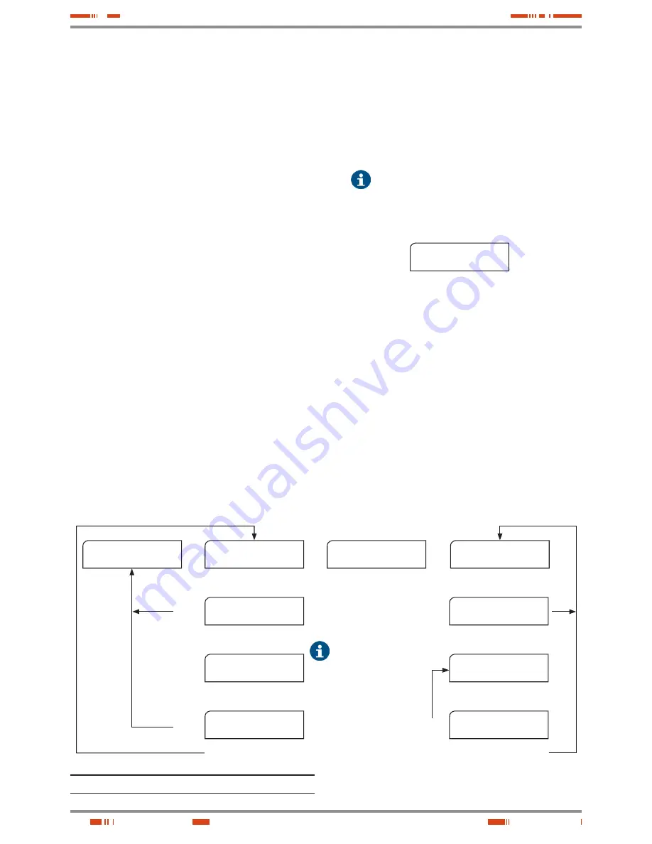
key), see Fig. 44:
UPS: Normal, Invert.
CFG: Paral. -------
screen 0.1
Where:
First row corresponds the UPS status.
And the second to the UPS hierarchy relating to the rest of
the system, which is dynamic depending on the status of
the rest of the equipments:
–
«Paral. Mst. Byp» bypass Master of the parallel system.
By default, the first UPS starting up the inverter ac-
cording to the established procedure.
–
«Paral. Slv. By.Rsv» reserved bypass Slave. Initially cor-
responds to the equipment with the highest address ex-
cepting the one from «bypass Master». In case of failure
of the Master, it will take its functions.
–
«Paral. Slv. Byp» bypass Slave of the parallel system
(systems with more than two equipments only). It will
become as «reserved bypass Slave», when it practise
as «bypass Master». In systems with more than three
USER MANUAL


