22
SALICRU
MANUAL BYPASS
AC OUTPUT
BYPASS
STATIC
SWITCH
INVERTER
DC-LINK
BATTERY
CHARGER
BATTERY PACK
AC INPUT
BYPASS
LINE
RECTIFIER-BOOSTER
Fig. 13.
UPS power flow stopped (but supplying the loads
via the bypass).
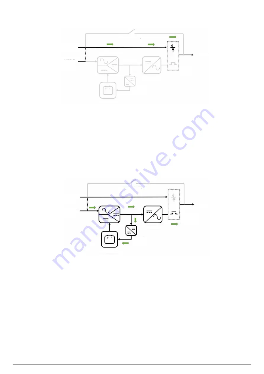
4.5.1. Normal mode.
For the UPS to work in normal mode, there must be an input
network (input switch activated), output switch activated
(supply for the loads), and there must be batteries in the unit or
connected in an external cabinet.
In this double conversion mode, the rectifier is powered by
the AC network, supplying direct voltage to the inverter (DC
bus). The inverter converts the DC voltage into a stabilised sine
wave, connecting to the loads via its static switch. The rectifier
also supplies voltage to the battery charger, which keeps the
batteries in an optimal state of charge.
It is the operating status with the highest protection for the
loads, as it applies "clean" voltage to them independently of the
input voltage, and with the battery power available in case an
AC network fault occurs.
MANUAL BYPASS
AC OUTPUT
BYPASS
STATIC
SWITCH
INVERTER
DC-LINK
BATTERY
CHARGER
BATTERY PACK
AC INPUT
BYPASS
LNE
RECTIFIER-BOOSTER
Fig. 14.
UPS power flow in normal mode.
4.5.2. Battery mode
In the event of an AC power supply fault, the rectifier-booster
switches its input power source from the AC network to the
battery without interruption. The battery voltage decreases ac-
cording to the discharge current value, but the rectifier-booster
is responsible for keeping the direct voltage to the inverter input
within the nominal working values.
If the supply is restored before the batteries are completely dis-
charged, the system will return to normal operation automatically:
rectifier operating in AC/DC conversion, charger charging batteries,
inverter continues operating.
Otherwise, as soon as the batteries reach the discharge limit
(end of autonomy), the inverter switches off, and if the unit
has a common input for the rectifier and the bypass, the power
supply of the load is interrupted ("black-out"). For units that
have a bypass line that is independent of the rectifier AC input,
if, upon reaching the battery discharge limit, the voltage in the
bypass line is within the tolerance limits, the power supply of
the load is transferred to this emergency line.
After a stop due to the end of autonomy, when the power supply
is restored, the rectifier restarts the charging of the batteries.
Likewise, if the power supply of the loads was interrupted
(common bypass to rectifier input), they are initially supplied via
the static bypass switch. The inverter will then restart and will
reconnect to the output.
Summary of Contents for SLC CUBE4
Page 1: ...30 80 kVA USER MANUAL...
Page 66: ...66 SALICRU...
Page 67: ...67 SLC CUBE4 UNINTERRUPTIBLE POWER SUPPLY SYSTEM USER MANUAL...
Page 68: ...68 SALICRU...
Page 69: ...69 SLC CUBE4 UNINTERRUPTIBLE POWER SUPPLY SYSTEM USER MANUAL...


