25
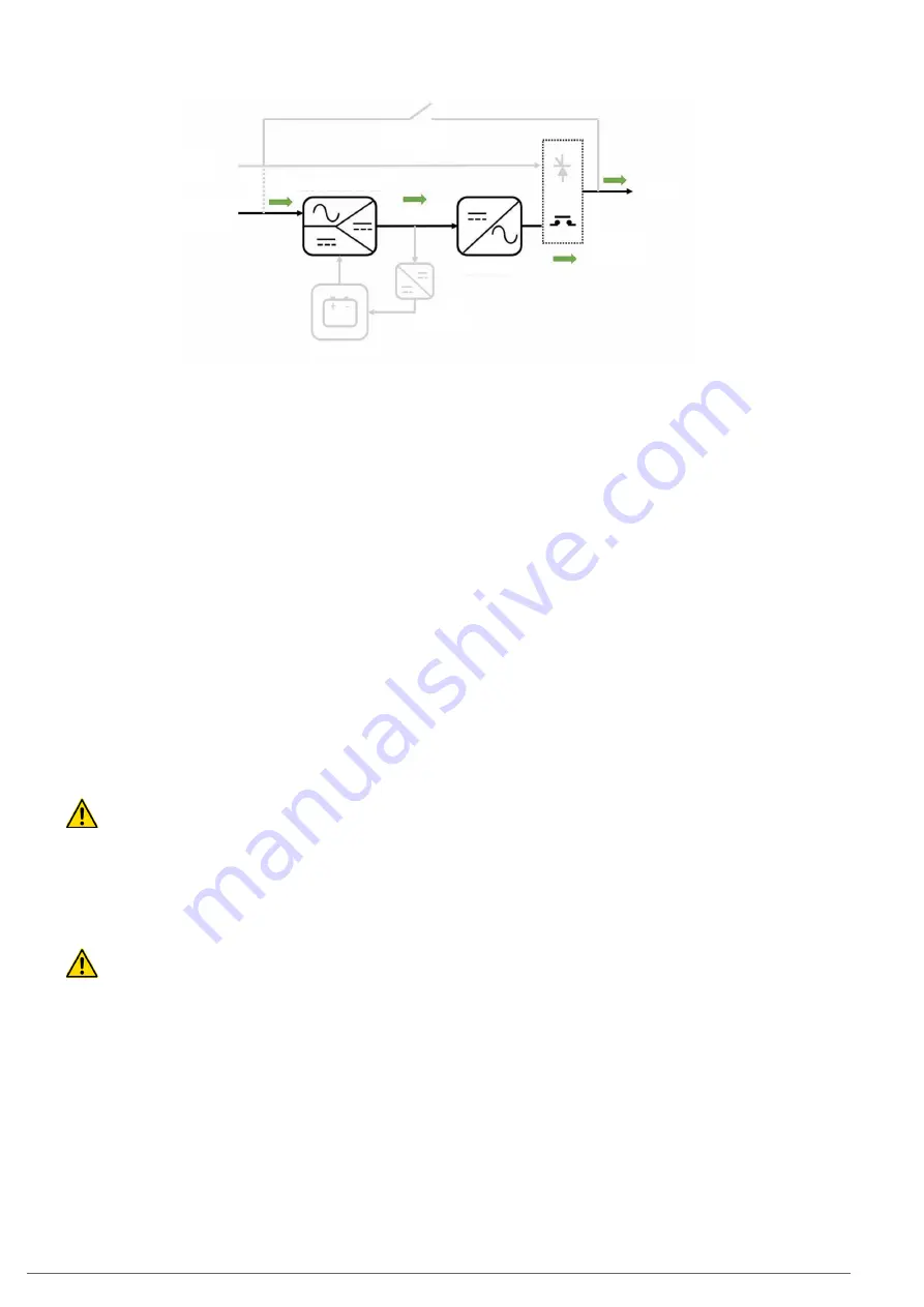
MANUAL BYPASS
AC OUTPUT
BYPASS STATIC
SWITCH
INVERTER
DC-LINK
BATTERY
CHARGER
BATTERY PACK
AC INPUT
BYPASS
LINE
RECTIFIER-BOOSTER
Fig. 19.
UPS power flow in frequency converter mode.
4.6. OPERATION AND CONTROL DEVICES
The operation and control devices allow the UPS user/operator
to carry out the following actions, among others:
•
Unit start-up.
•
Special operations (such as switching to bypass mode).
•
Maintenance and repair interventions (maintenance bypass
mode).
•
Monitoring of parameters and measurements "in-situ" via
the unit screen (for example: consumption, load percent-
ages, etc.).
•
Remote monitoring and signalling (external to the UPS):
Digital inputs corresponding to external switchgear
(e.g. external manual bypass).
Activation of UPS operating mode indication relays (e.g.
UPS in battery mode indication relay).
RS232/RS485/USB communication ports.
Communication slots (SNMP, Nimbus, relay extension,
extension of functions).
The use of UPS operation and control devices is only
intended for authorised staff. It is recommended to
check the training of staff who are responsible for the use and
maintenance of the system.
4.6.1. Switches
The switches arranged in the UPS are used to isolate the unit
from the AC power supply, the storage batteries and the load.
Presence of voltage at unit terminals.
The disconnect switches do not fully isolate the UPS,
as the AC voltage is still present at the UPS input terminals.
Before carrying out any maintenance on the unit, it is neces-
sary to:
•
Fully isolate the UPS by opening (disconnecting) the ex-
ternal switches.
•
Wait for at least 5 minutes to allow the capacitors to dis-
charge.
The SLC CUBE4 UPS has the following switches (some are op-
tional, as indicated):
•
Rectifier AC input line switch (common to the bypass line, if it
is not a unit with an optional separate bypass): this switch is a
circuit breaker for models up to 50 kVA, and a disconnect switch
for 80 kVA and higher.
•
AC bypass line switch, optional for units with a circuit
breaker-type separate bypass.
•
Disconnect switch for maintenance bypass. This switch will
remain mechanically locked (against activation) during op-
eration in normal mode.
•
Output circuit breaker switch. It allows the voltage supplied
by the UPS to be connected to the loads, or for them to be
isolated if necessary.
•
Battery disconnect switch for 50 kVA models and higher.
It allows the UPS to be isolated from the power supply
provided by the batteries, whether they are internal or ex-
ternal. On models of up to 40 kVA, the UPS can be isolated
from the batteries by disconnecting a connector that is
easily accessible by the operator (whether they are internal
batteries -
Fig. 1
Detail A
-
, or external -
Fig. 3 and Fig. 4
).
In addition, in external battery cabinets, there will be a con-
nection and disconnection method
(Q8)
.
4.6.2. Control panel with touchscreen
The control panel of the UPS is fully integrated into a graphic
touchscreen ("touch panel"). Some of the characteristics of this
screen are as follows:
•
5” diagonal screen size.
•
16:9 aspect ratio.
•
Resolution of 800 x 480 pixels.
•
65 K colours.
•
Capacitive touch sensor.
This control panel allows:
•
Monitoring of measurements and operating parameters.
•
Display and acknowledgement of alarms and statuses (ac-
tive and passed).
•
Modification of basic operating configurations and parameters.
•
Change of UPS operating mode (normal, bypass, ECO mode,
battery test).
4.6.3. External interface and communications
The unit's interface with the outside consists of various dedi-
cated input and output signals, and different ports and com-
munication slots.
SLC CUBE4
- UNINTERRUPTIBLE POWER SUPPLY SYSTEM
-
USER MANUAL
Summary of Contents for SLC CUBE4
Page 1: ...30 80 kVA USER MANUAL...
Page 66: ...66 SALICRU...
Page 67: ...67 SLC CUBE4 UNINTERRUPTIBLE POWER SUPPLY SYSTEM USER MANUAL...
Page 68: ...68 SALICRU...
Page 69: ...69 SLC CUBE4 UNINTERRUPTIBLE POWER SUPPLY SYSTEM USER MANUAL...


