33
In the same documentation and for each configuration, the
information for "N" parallel units is available.
• Connect the output cables to the respective terminals ac-
cording to the configuration of the available unit.
For parallel systems, the connections that go from each
unit to the board must be repeated.
Connection of the three-phase output:
Connect the loads to the U-V-W-N output terminals, ob-
serving the order of the phases and neutral indicated on
the unit's labelling and in this manual. If the order of the
phases is not observed, the unit will not work.
When there are discrepancies between the labelling and the
instructions in this manual, the labelling will always prevail.
• With regards to the protection that must be fitted on the
protection board or manual bypass output, we recommend
dividing the output power between at least four lines.
Each one will have a protection circuit breaker of a suit-
able value. This type of output power distribution will en-
sure that a fault in any of the machines connected to the
unit that causes a short circuit only affects the line that
is faulty. The other connected loads will have guaranteed
continuity due to the protection only being tripped on the
line affected by the short circuit. .
5.2.4. Connection of the unit's battery terminals to those of
the battery module (
Fig. 10 and Fig. 11)
.
•
As this unit has protection against class I electric
shocks, it is essential to install a protective earth
conductor (connect earth ( )). Connect this conductor to
the earth terminal before supplying voltage to the input
terminals.
• The original factory battery circuit type is open.
–
+
•
Do not handle the battery connectors and/or the dis-
connect switch when the unit is running.
Do not
disconnect under load.
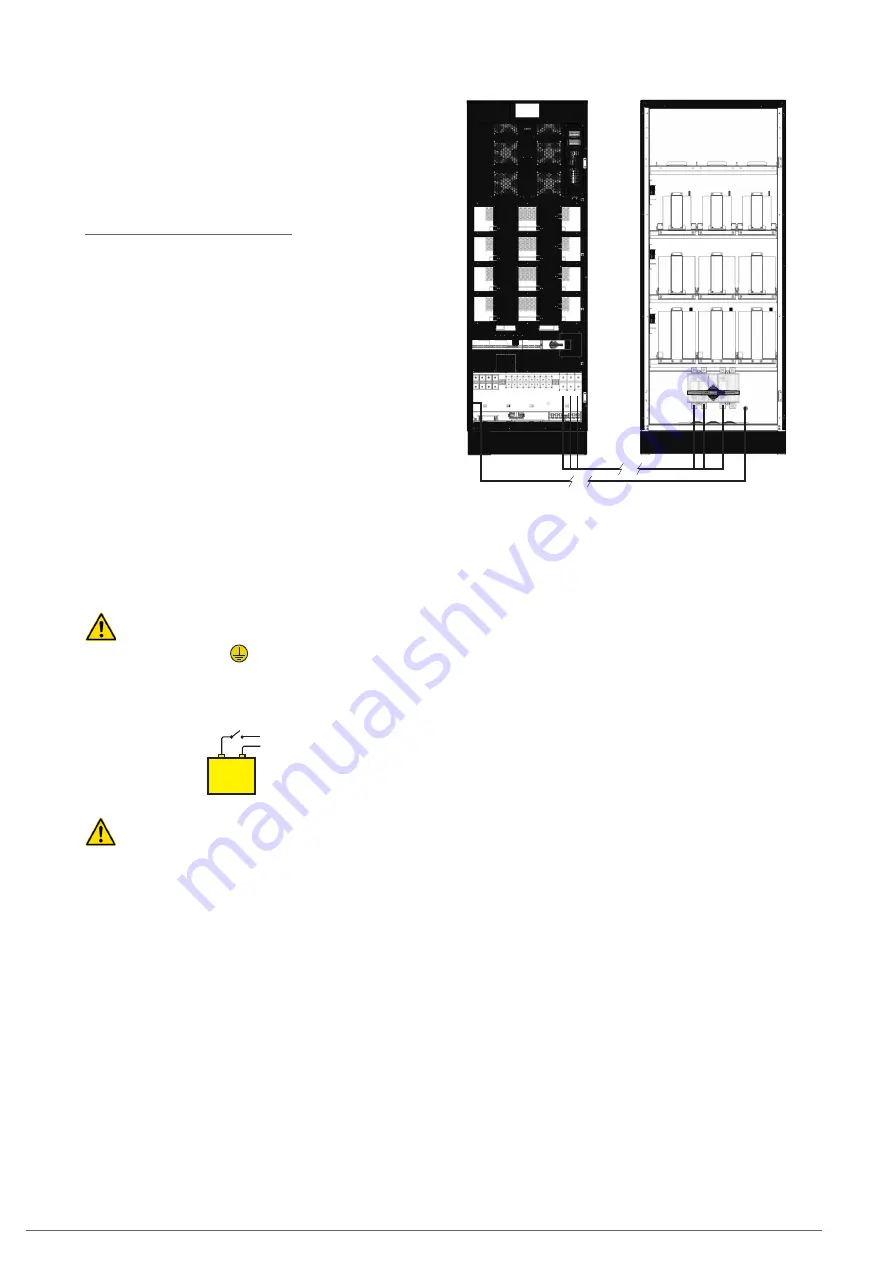
• The battery cabinet is connected to a B1 model UPS using
the cable bundle supplied, connecting one end to the UPS
terminals and the other to the battery module terminals,
observing the polarity indicated on the labelling of each
element and in this manual. Observe the connections ac-
cording to cable colour: a UPS positive colour to a battery
cabinet positive; another UPS negative colour to a battery
negative; another UPS neutral colour to the battery middle
tap (N). Use the green-yellow cable to interconnect the
earth connections, see
Fig. 28
.
T
T
+ N –
+ N –
Fig. 28.
Connection between the UPS and a battery
cabinet.
• For extended autonomy where
more than one module or
battery cabinet
is supplied, the connection will always be
in parallel between them and the unit (see
Fig. 29).
.
That is, a cable of the same colour, from the UPS negative to
the negative of the first battery cabinet and from this to the
negative of the second battery cabinet, and so on. Proceed
in the same way for the connection of the positive cable, for
the middle tap cable (N) and for the green-yellow earth con-
nection.
The connection of the batteries to the UPS is the same as
if it were a single unit, due to the fact that it belongs or is
connected to a parallel system, as each set of batteries is
connected directly to its UPS by default, irrespective of the
number of battery cabinets.
SLC CUBE4
- UNINTERRUPTIBLE POWER SUPPLY SYSTEM
-
USER MANUAL
Summary of Contents for SLC CUBE4
Page 1: ...30 80 kVA USER MANUAL...
Page 66: ...66 SALICRU...
Page 67: ...67 SLC CUBE4 UNINTERRUPTIBLE POWER SUPPLY SYSTEM USER MANUAL...
Page 68: ...68 SALICRU...
Page 69: ...69 SLC CUBE4 UNINTERRUPTIBLE POWER SUPPLY SYSTEM USER MANUAL...


