38
SALICRU
d.
Units with external batteries (or shared with in-
ternal ones), with an internal (
Q6
) or external bat-
tery switch (
Q3
) (50 kVA, 60 kVA, 80 kVA)
: set these
switches to "On", which are accessed by opening the
front door of the unit (see
Fig. 7 and Fig. 8)
. Also, set
the external battery cabinet switch to "On"
(Q8),
(see
Fig. 10 and Fig. 11
).
6.
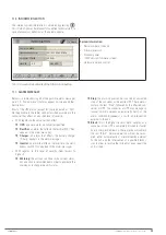
Press the "Status and Control" icon
You are
on the screen described in
7.4
.
7.
If the UPS stopped due to a power loss
(disconnection
of the AC input and batteries, or end of autonomy),
having
been operating in normal mode just before this, the
UPS will restart automatically at this point
, and this can
be checked in the "UPS Status" box: go to point 8 of this
section.
8.
If the UPS does not start automatically ("UPS Status"
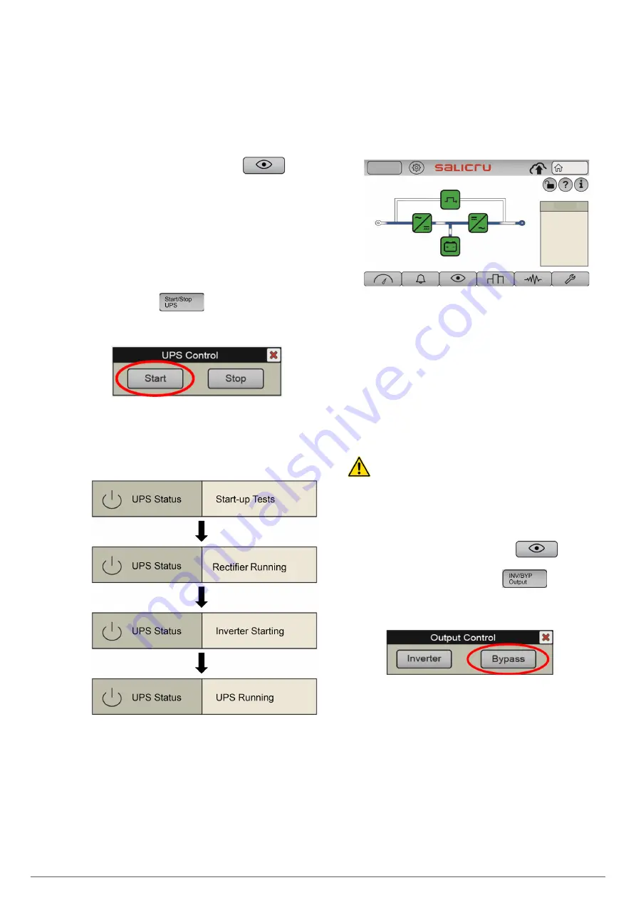
remains as "UPS ON / Pending” ), press the "Start/
Stop UPS" icon
9.
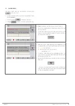
The "UPS Control" pop-up box appears, with the "Start"
and "Stop" options. Press “Start”.
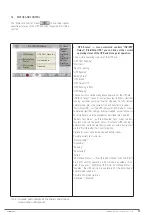
Fig. 32.
"UPS Control" pop-up window. Press "Start"
10.
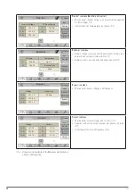
Check the start-up phases in "UPS Status" ("Status
and Control" submenu, see
7.4
). Check that the fol-
lowing phases are fulfilled.
Otherwise (the final status "UPS Running" is not reached),
or if the process is interrupted, check the Alarms menu, and
inform the qualified Technical Service if necessary.
11.
Set the switch corresponding to the UPS output on
the control panel (external) to "On".
12.
Set the output switch of the UPS to "On" (
Q2
).
The unit
supplies voltage at the output terminals of the control
panel.
13.
Start the loads (or set their switches on the distribu-
tion board to "On", if any) progressively.
14.
The system is operating fully, and the loads are pro-
tected by the UPS
. You can obtain basic information on
the main screen of the control panel (synoptic, input and
output voltages, system load percentages).
Log In
Home
Load
2020-09-15
07:28:06
L1
231. 8
L2
233. 5
L3
232. 8
L1
229. 6
L2
229. 4
L3
230. 1
L1
0. 2%
L2
1. 0%
L3
0. 2%
Tot
0. 2%
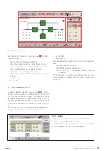
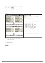
Fig. 33.
Main screen in normal operation. The power flow
should match the one shown: input supplies rectifier;
this simultaneously supplies the inverter and the
battery charger; the inverter supplies power to the
output loads.
6.1.4. Procedure for transferring to bypass mode
On specific occasions, for example temporarily while awaiting
an intervention on the UPS due to a fault, or as indicated by the
Service Technician, it may be useful to manually transfer the
UPS to bypass mode (see
4.5.3
).
In this operating mode, the loads will not be protected
against power outages and line disturbances.
With the UPS operating in normal mode (synoptic shown in
Fig.
33
, and in the "Status and Control" submenu you can see that
the "UPS Status" shows "UPS Running"), in order to switch to
bypass mode, proceed as follows:
1.
Press the "Status and Control" icon
You are
on the screen described in
7.4
.
2.
Press the "INV/BYP Output" icon
3.
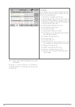
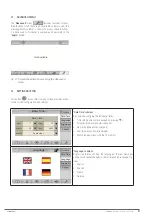
The "UPS Control" pop-up box appears, with the "In-
verter" and "Bypass" options. Press “Bypass”.
Fig. 34.
"Output Control" pop-up window. Press "Bypass".
4.
The loads switch to being supplied directly from
the static bypass line
. The unit's inverter is shutdown
(waiting), but the rectifier and charger are operating (the
battery charge is maintained). A new "UPS Unit in Bypass"
alarm appears, warning us of the current "risk" situation for
critical loads.
Summary of Contents for SLC CUBE4
Page 1: ...30 80 kVA USER MANUAL...
Page 66: ...66 SALICRU...
Page 67: ...67 SLC CUBE4 UNINTERRUPTIBLE POWER SUPPLY SYSTEM USER MANUAL...
Page 68: ...68 SALICRU...
Page 69: ...69 SLC CUBE4 UNINTERRUPTIBLE POWER SUPPLY SYSTEM USER MANUAL...


