41
At this point, the unit will stop completely
(the control
panel screen switches off).
14.
Set the input switch of the UPS to "Off" (
Q1
).
15.
In units with a separate static bypass input, set the
corresponding bypass switch to "Off" (
Q4
).
The unit is now in maintenance bypass operating mode,
described in
4.5.4
.
DANGER OF ELECTRIC SHOCK: before any repair
or maintenance operation inside the unit, to be
carried out solely and exclusively by the qualified Tech-
nical Service, wait for approximately 5 minutes from this
moment, the required time for the electrolytic capacitors
to discharge.
In addition, any repair work on the UPS will require
the neutral disconnect mechanism inside the unit
to be activated by the technician, in order to prevent the
installation's differential circuits from tripping, causing
the supply to the load(s) to be disrupted.
6.3.2. Transferring back to normal mode (from maintenance
bypass mode)
To recover the normal operating mode of the UPS, while the
unit is in the bypass operating mode (see
6.3.1
above), strictly
follow the procedure described in this section.
If repair work has been carried out inside the UPS,
before continuing, make sure that all elements, in-
ternal connections, fixing screws, etc., are correctly as-
sembled. The neutral disconnect mechanism must also
be in its normal position, ensuring the continuity of this
conductor to the interior of the UPS. With regards to the
external cables of the UPS, if they have been handled,
make sure they have been returned to their normal posi-
tion and with the correct tightening torque.
1.
Set the switch corresponding to the UPS input on the
panel to "On"
. If there is a separate bypass line for the
UPS, also set this switch on the control panel to "On".
2.
Set the input switch of the UPS to "On" (
Q1
).
3.
In units with a separate static bypass input, set the
corresponding bypass switch to "On" (
Q4
).
4.
Connect the batteries:
a.
Units with internal batteries
: connect the 3-pole bat-
tery connector (
Fig. 1
Detail A
,
on the front), or set the
battery switch to "On" (
Q6
, on the front), as applicable.
b.
Units with external batteries:
connect the battery cir-
cuit breaker on 50 kVA, 60 kVA and 80 kVA units (
Q3
, on
the front), or connect the external battery cables on the
back of 30 kVA and 40 kVA units, as applicable. Also, set
the external battery cabinet switch to "On"
(Q8)
.
c.
Units with shared internal and external batteries
:
carry out points
a.
and
b.
described above one after
the other.
5.
Set the switch corresponding to the UPS output on
the control panel (external) to "On".
6.
Set the output switch of the UPS to "On" (
Q2
).
7.
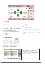
Check that the UPS supplies voltage simultaneously
to the output via the maintenance bypass switch and
the static bypass
: check the existing "UPS Unit in bypass"
and "Mainten. Byp Closed" alarms, and the synoptic on the
main control panel screen, as shown in
Fig. 37
.
8.
Only at this point proceed to set the maintenance by-
pass switch on the control panel to "Off"
. If applicable,
replace its mechanical lock.
9.
Set the maintenance bypass switch of the UPS to "Off"
(
Q5
).
10.
Replace the mechanical lock of the UPS manual by-
pass switch
: screw the metal cover in using the screws
provided (see
Fig. 39 and Fig. 40
).
11.
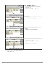
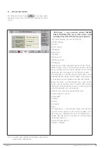
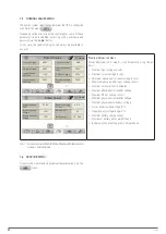
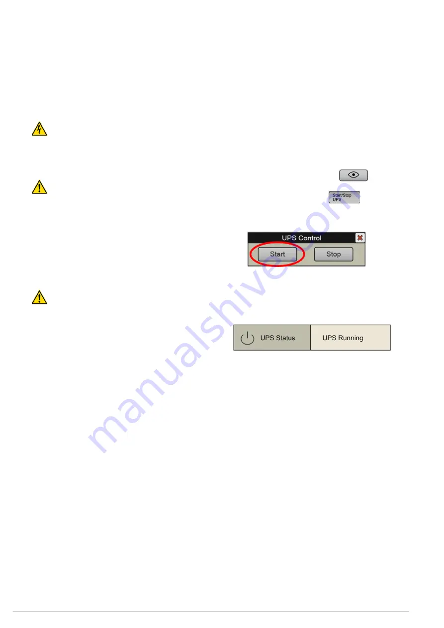
Press the "Status and Control" icon
You are
on the screen described in
7.4
.
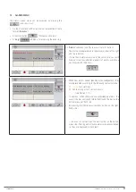
12.
Press the "Start/Stop UPS" icon
13.
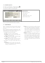
The "UPS Control" pop-up box appears, with the "Start"
and "Stop" options. Press “Start”.
Fig. 41.
"UPS Control" pop-up window. Press “Start”.
14.
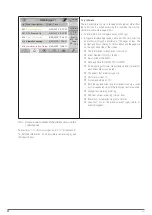
Check the start-up phases in "UPS Status" ("Status
and Control" submenu, see
7.4
), and check that the
final status "UPS Running" is reached.
The system goes back to operating in normal mode,
and the loads are protected by the UPS against distur-
bances and potential supply interruptions.
6.4. EMERGENCY STOP (EPO)
The unit is equipped with an emergency stop circuit (EPO - "Emer-
gency Power Off"). This shutdown may be necessary to prevent
dangerous situations for the unit itself or for the loads (fire,
flooding, electric shock, etc.).
The functionality of this circuit, when activated, is:
•
To switch off all UPS converters (rectifier, charger and in-
verter).
•
To ensure no voltage is supplied to the loads.
In the
SLC CUBE4
UPS, this circuit is included on the 2-pin
strip of the unit interface (see
Detail A
Fig. 1 and
Detail C
Fig.
9)
. On this strip there is a wire bridge, supplied from the factory,
"closing" the EPO circuit. In the final installation, this bridge
can be replaced by a remote button or switch, which closes the
circuit in standby (normal operation of the UPS), and opens the
circuit when activated (activation of the emergency stop).
SLC CUBE4
- UNINTERRUPTIBLE POWER SUPPLY SYSTEM
-
USER MANUAL
Summary of Contents for SLC CUBE4
Page 1: ...30 80 kVA USER MANUAL...
Page 66: ...66 SALICRU...
Page 67: ...67 SLC CUBE4 UNINTERRUPTIBLE POWER SUPPLY SYSTEM USER MANUAL...
Page 68: ...68 SALICRU...
Page 69: ...69 SLC CUBE4 UNINTERRUPTIBLE POWER SUPPLY SYSTEM USER MANUAL...


