42
SALICRU
6.4.1. Activation of the emergency stop (EPO).
Take into account that the activation of this circuit will
cause a supply cut for the loads, and they will therefore
switch off.
1.
"Open" the circuit on the strip
: remove the wire bridge
or set the remote button that replaced this bridge to "ON".
2.
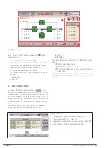
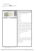
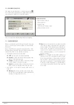
A new "Emergency Stop" alarm appears on the control
panel, and any power flow of the synoptic disappears
from the main screen.
Log In
Home
Load
2020-09-15
07:28:06
L1
231. 8
L2
0. 0
L3
0. 1
L1
0. 8
L2
0. 9
L3
0. 4
L1
0. 0%
L2
0. 0%
L3
0. 0%
Tot
0. 0%
Fig. 42.
Main screen with EPO emergency stop activated.
No power flow represented, there is no output
voltage.
3.
If it is necessary to completely stop the UPS at this
point, proceed in the same way as
6.2
. In short:
a.
Set the switch corresponding to the UPS output on the
control panel (external) to "Off".
b.
Set the output switch of the UPS to "Off"
(Q2).
c.
Disconnect the batteries.
d.
Set the UPS input switch on the control panel to "Off".
If there is a separate bypass line for the UPS, also set
that switch to "Off".
e.
The unit will stop completely.
f.
If possible, cut off the general power supply to the con-
trol panel.
g.
Set the input switch of the UPS to "Off"
(Q1)
.
h.
In units with a separate static bypass input, set the cor-
responding bypass switch to "Off"
(Q4)
.
6.4.2. System restoration after an emergency stop (EPO).
1.
If the system is completely stopped (all UPS and external
control panel switches set to "Off", open EPO circuit or re-
mote button activated):
a.
"Close" the circuit on the strip
: replace the wire
bridge, or set the remote button that replaced this
bridge to "Off".
b.
From here, proceed as described in
"6.1.3. Generic
start-up procedure (normal mode)"
, and ignore the fol-
lowing steps described in this section.
2.
If the UPS is powered (the UPS and external control panel
switches required for normal operation are set to "On", the
batteries are connected), but the EPO circuit is open or the
remote button is activated: the UPS will be powered, the
"Emergency Stop" alarm will be present, all converters will
be stopped and no voltage will be supplied to the loads. To
restore normal operation:
a.
"Close" the circuit on the strip
: replace the wire
bridge, or set the remote button that replaced this
bridge to "Off".
b.
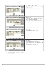
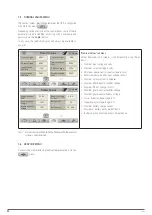
Press the "Status and Control" icon
You
are on the screen described in
7.4
.
c.
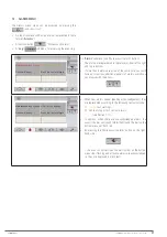
Press the "Start/Stop UPS" icon
d.
The "UPS Control" pop-up box appears, with the
"Start" and "Stop" options. Press "Stop".
Fig. 43.
"UPS Control" pop-up window. Press "Stop".
e.
The loads switch to being supplied directly from
the static bypass line. Check that the "Emergency
Stop" alarm disappears and a new "UPS Unit in
bypass" appears
. Also check that the unit's synoptic
corresponds to the one in
Fig. 37
(unit in bypass mode).
f.
Press the "Status and Control" icon
You
are on the screen described in
7.4
.
g.
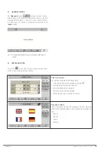
Press the "Start/Stop UPS" icon
h.
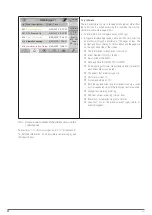
The "UPS Control" pop-up box appears, with the
"Start" and "Stop" options. Press “Start”.
Fig. 44.
"UPS Control" pop-up window. Press “Start”.
i.
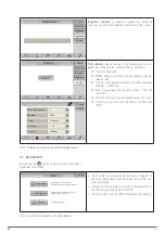
Check the start-up phases in "UPS Status" ("Status
and Control" submenu, see
7.4
), and check that the
final status "UPS Running" is reached
.
The system goes back to operating in normal mode,
and the loads are protected by the UPS against dis-
turbances and potential supply interruptions.
Summary of Contents for SLC CUBE4
Page 1: ...30 80 kVA USER MANUAL...
Page 66: ...66 SALICRU...
Page 67: ...67 SLC CUBE4 UNINTERRUPTIBLE POWER SUPPLY SYSTEM USER MANUAL...
Page 68: ...68 SALICRU...
Page 69: ...69 SLC CUBE4 UNINTERRUPTIBLE POWER SUPPLY SYSTEM USER MANUAL...


